Driver for switch and a method of driving the same

a technology of driver and switch, applied in the field of power electronics, can solve the problems of affecting the operation of the switch, and the inability to adapt to the circuit, and the difficulty of achieving the effect of circuit modification, and achieving the effect of avoiding the failure of the switch

Active Publication Date: 2008-01-24
INTEL CORP
View PDF88 Cites 71 Cited by
  • Summary
  • Abstract
  • Description
  • Claims
  • Application Information

AI Technical Summary

Problems solved by technology

The aforementioned structures that form the MOSFETs, however, present new design challenges associated with maintaining voltage limits of the control signals such as a gate voltage adapted to control the conduction periods of the switches.
In other words, when the input voltage to the power converter which is translated into the drive signal to the switch under certain conditions as described above exceeds the gate voltage limit thereof, the switch may be damaged and fail.
Thus, the totem pole driver and other presently available drivers are typically not practical without circuit modifications for applications wherein the switch to be driven exhibits a smaller gate voltage limit than the input voltage of the power converter from the gate terminal to the source terminal thereof.
Another level of complexity arises when the switch to be driven and the driver are referenced to different voltages.
Thus, drivers for applications employing switches with a control voltage limit (i.e., a control voltage substantially less than an input voltage of the power converter) are often allocated space that is not easily integrable with the rest of the integrated circuit.
Consequently, controllers with such drivers add measurable cost to a design of a power converter beyond the voltage sourcing functionality thereof.

Method used


Image

  • Driver for switch and a method of driving the same
  • Driver for switch and a method of driving the same
  • Driver for switch and a method of driving the same

Examples


Embodiment Construction

[0026]The making and using of the presently preferred embodiments are discussed in detail below. It should be appreciated, however, that the present invention provides many applicable inventive concepts that can be embodied in a wide variety of specific contexts. The specific embodiments discussed are merely illustrative of specific ways to make and use the invention, and do not limit the scope of the invention.

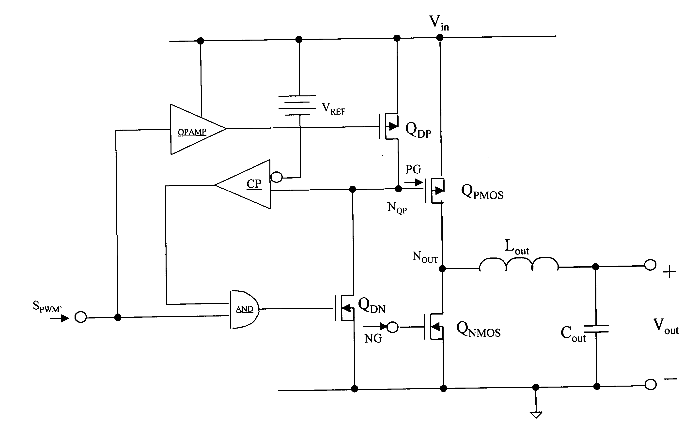
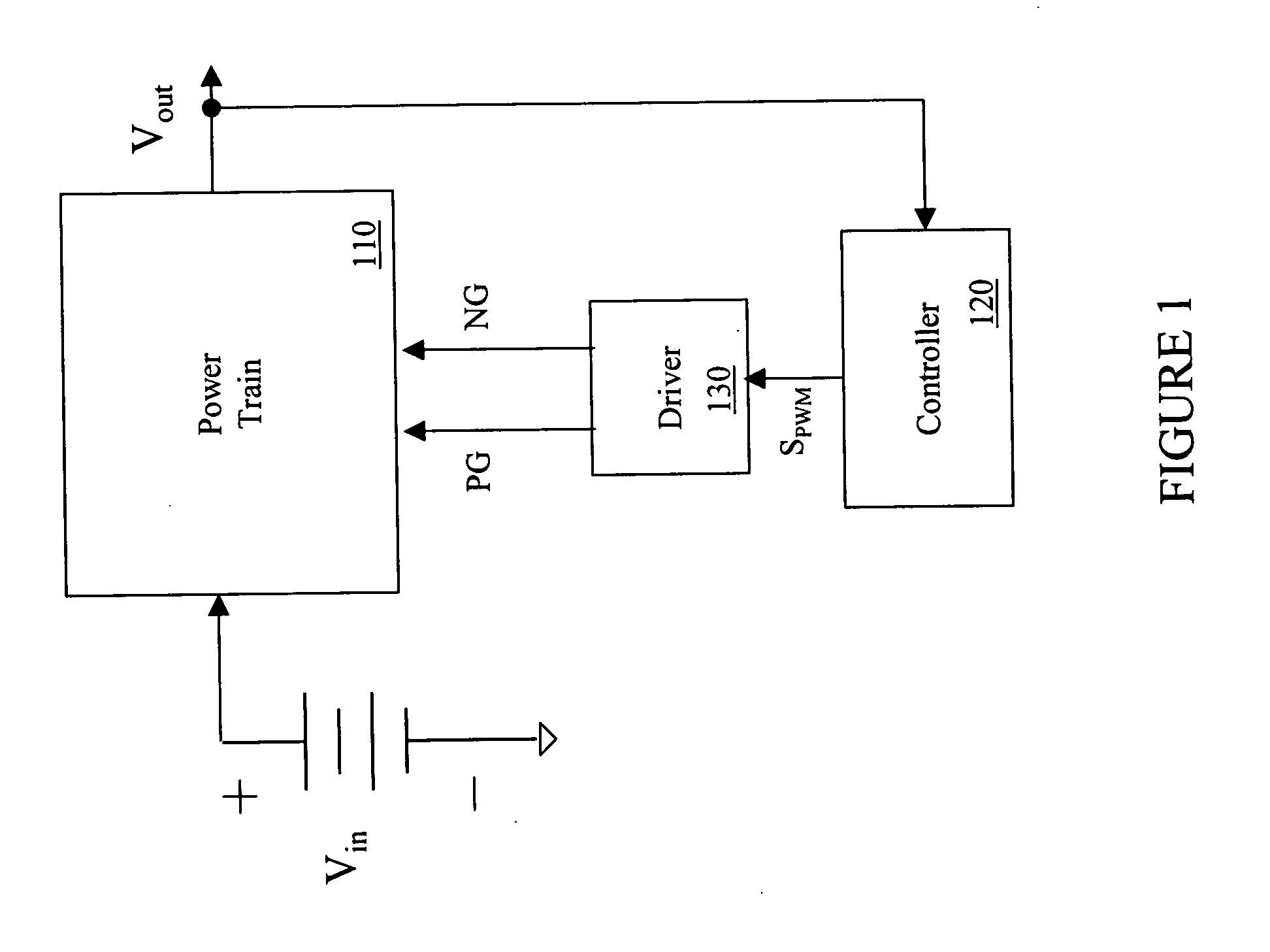
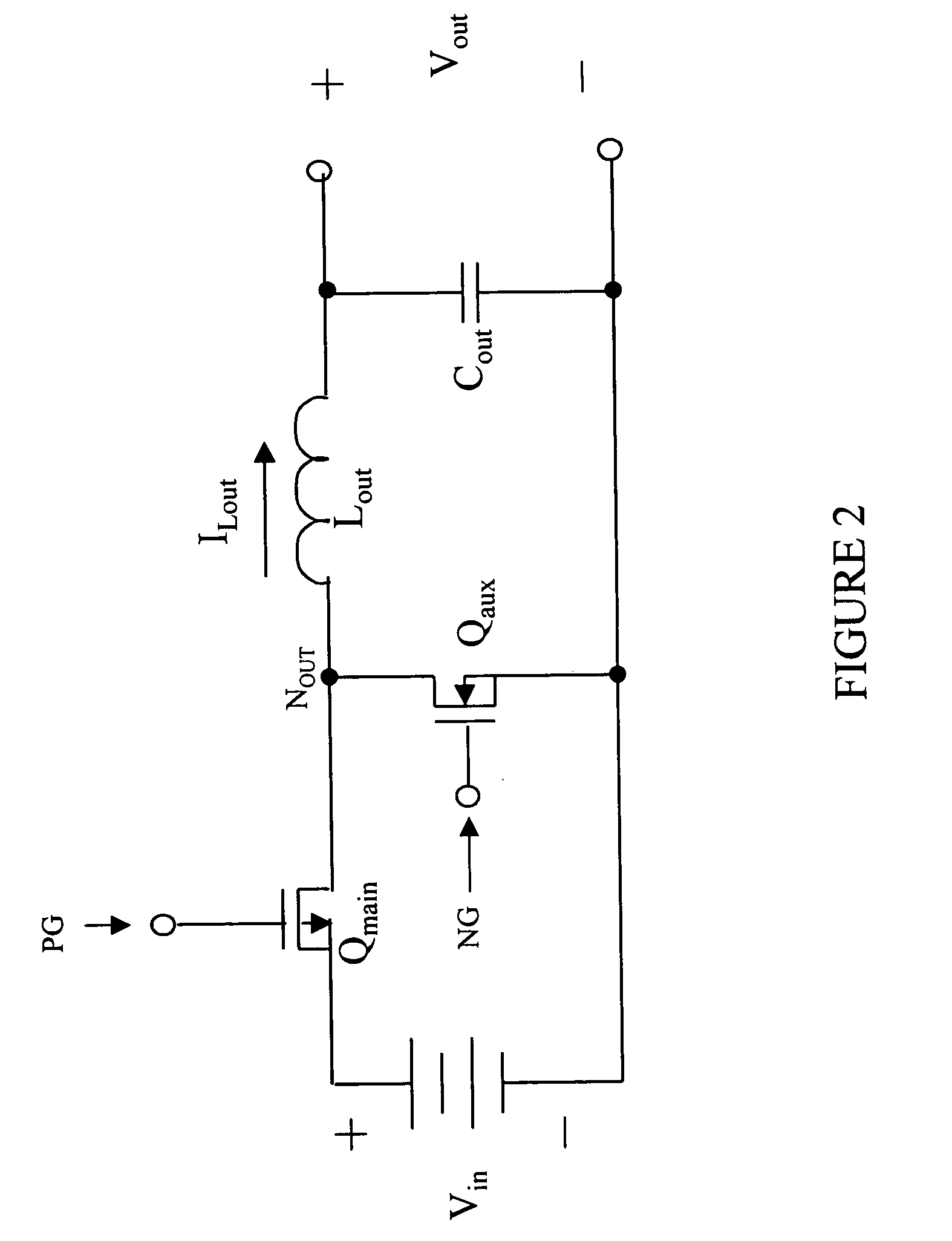
[0027]The present invention will be described with respect to preferred embodiments in a specific context, namely, a driver for a power converter, method of driving a switch thereof and a power converter employing the same. The principles of the present invention, however, may also be applied to all types of power supplies employing various conversion topologies that may benefit from a driver that takes into account a control voltage limit associated with a switch [e.g., the gate voltage limit for a metal-oxide semiconductor field-effect transistor (“MOSFET”)] of the power co...


PUM


Abstract

A driver for a switch, a related method of driving the switch, and a power converter employing the same. In one embodiment, the driver includes switching circuitry having a driver switch referenced to a voltage level and configured to provide a drive signal to a control terminal of a power switch referenced to another voltage level and subject to a control voltage limit. The driver also includes a comparator configured to change a state of the driver switch when a voltage at the control terminal passes a threshold voltage.

Description

TECHNICAL FIELD[0001]The present invention is directed, in general, to power electronics and, more specifically, to a driver for a switch, method of driving the same, and a power converter employing the same.BACKGROUND[0002]A switch mode power converter (also referred to as a “power converter”) is a power supply or power processing circuit that converts an input voltage waveform into a specified output voltage waveform. Controllers associated with the power converter manage an operation thereof by controlling the conduction periods of switches employed therein. Generally, controllers are coupled between an input and output of the power converter in a feedback loop configuration (also referred to as a “control loop” or “closed control loop”).[0003]Typically, the controller measures an output characteristic (e.g., an output voltage) of the power converter and based thereon modifies a duty cycle of the switches of the power converter. The duty cycle is a ratio represented by a conducti...

Claims


Application Information

Patent Timeline
Patent Type & Authority Applications(United States)
IPC IPC(8): H03B1/00
CPCH02M1/08H03F3/2171H03F2200/78H03K19/018521H03K17/6872H03K17/6874H03K17/08122
Inventor HANNA, JOHN E.
Owner INTEL CORP
Why Eureka
Try Eureka