Optical mouse

a mouse and optical technology, applied in the field of mouse, can solve the problems of low capture rate, high cost, difficult fabrication, etc., and achieve the effect of improving the accuracy of the optical mouse and reducing the probability of incorrect judgment of the optical mous

Inactive Publication Date: 2008-01-24
YOUNG OPTICS
View PDF5 Cites 7 Cited by
  • Summary
  • Abstract
  • Description
  • Claims
  • Application Information

AI Technical Summary

Benefits of technology

[0010]The present invention is directed to provide an optical mouse to improve the accuracy of the optical mouse in terms of image capture and to reduce the probability of incorrect judgment of the optical mouse.
[0011]The present invention is to provide an optical mouse using Michelson interference principle to improve the accuracy of the optical mouse in terms of image capture and to reduce the probability of incorrect judgment of the optical mouse.
[0014]As the light beam emitted from the light source is projected on the surface of an object vertically, and eventually is projected on the image sensor vertically, the image captured by the image sensor is not distorted. Therefore, the optical mouse of the present invention has higher operation accuracy as compared with the conventional optical mouse, and the probability of incorrect judgment of the image sensor thereof is lowered as well.

Problems solved by technology

In addition, the requirements for the optical characteristics of the surfaces of lens structures of the lens portion A and the lens portion B are quite strict, so it is difficult to fabricate, and the cost is high.
However, the intensity of the light beam captured by an image sensor is approximately one fourth of the original intensity of the light beam, and thus the brightness of the image captured by the image sensor is low, influencing the accuracy of the optical mouse in terms of image capture.
Moreover, the light guide body and the imaging lens in the optical system are integrated into one-piece, so it is difficult to fabricate, and the cost is high.

Method used


Image

  • Optical mouse
  • Optical mouse
  • Optical mouse

Examples


first embodiment

The First Embodiment

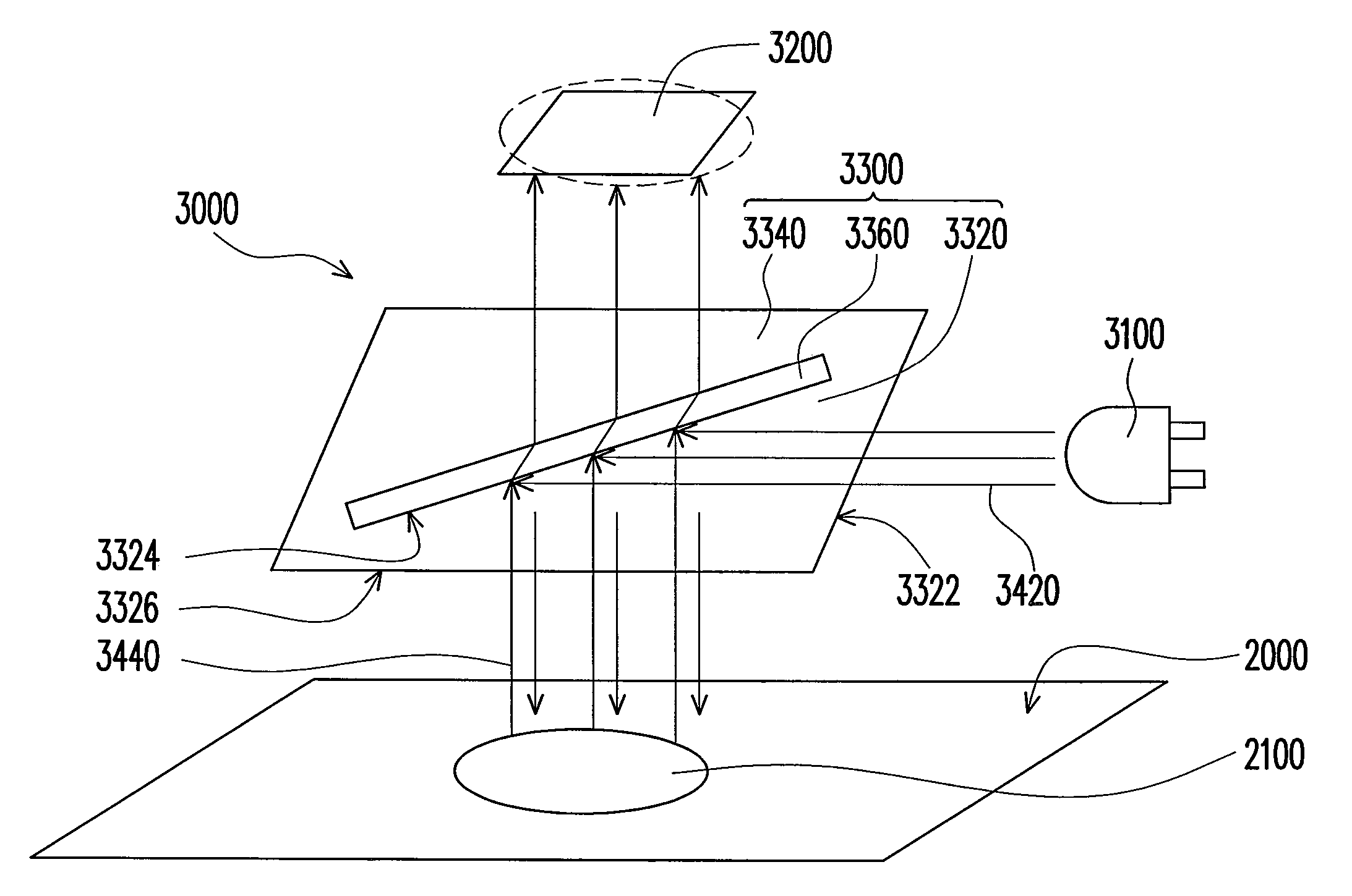
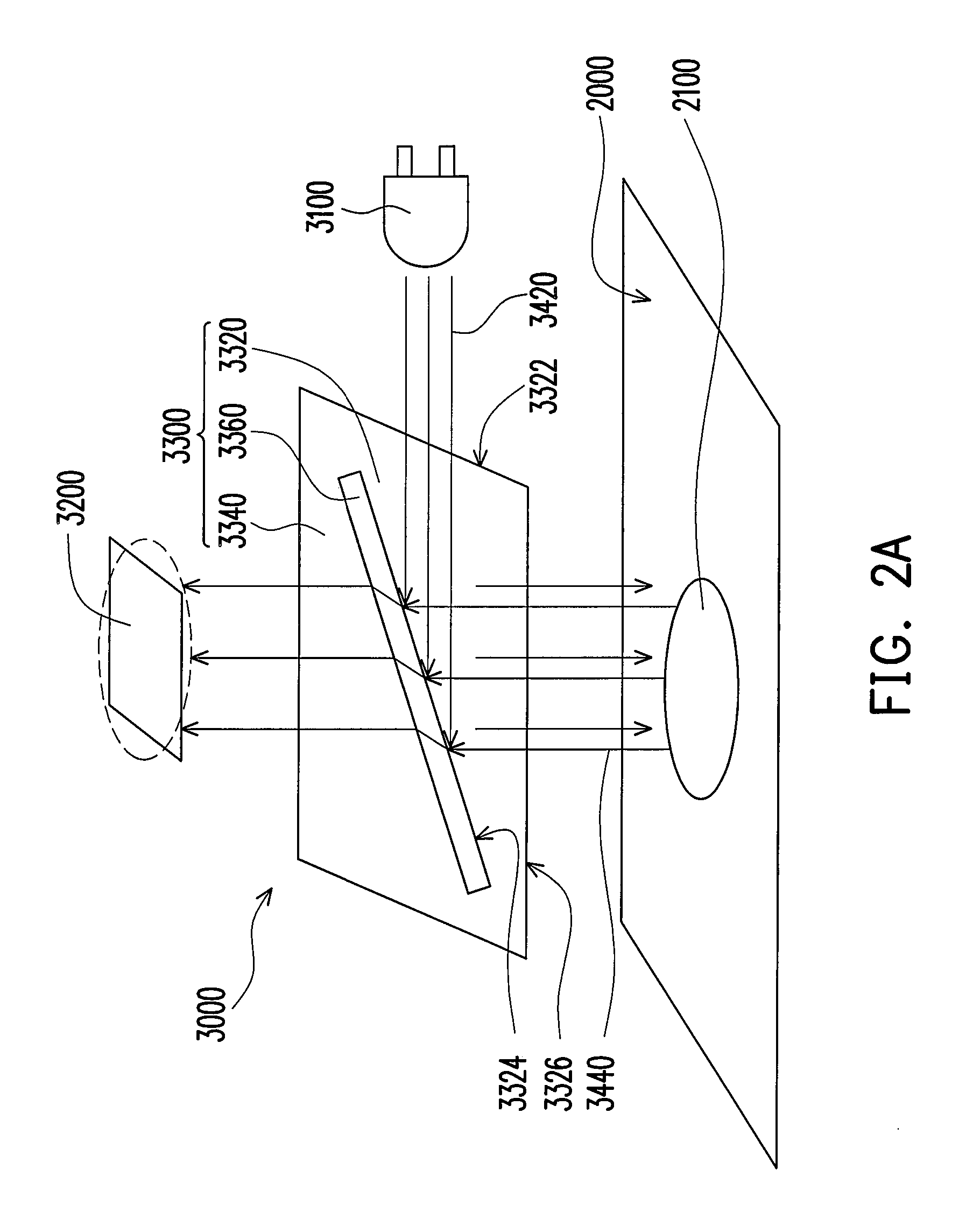
[0023]FIG. 2A is a schematic view of the optical system of the optical mouse according to the first embodiment of the present invention. Referring to FIG. 2A, the optical mouse is suitable for being put on a surface 2000, and the optical system 3000 includes a light source 3100, an image sensor 3200, and a prism 3300. The light source 3100 is, for example, a light emitting diode or a laser diode, and is suitable for emitting a light beam 3420. The image sensor 3200 is, for example, a CCD or a CMOS image sensor. The prism 3300 is, for example, a TIR prism.

[0024]The prism 3300 is disposed between the surface 2000 and the image sensor 3200, and is located on the optical path of the light beam 3420. The prism 3300 includes a first prism 3320, a second prism 3340, and a gap 3360. The first prism 3320 has a light-incident surface 3322, a total reflection surface 3324, and a light-emerging surface 3326. The light beam 3420 emitted from the light source 3100 enters the f...

second embodiment

The Second Embodiment

[0029]FIG. 3A is a schematic view of the optical system of the optical mouse according to the second embodiment of the present invention. Referring to FIG. 3A, the optical system 500a is suitable for being put on a surface 400, and includes a light source 510, an image sensor 530, a dichroic mirror 540, and a reflector 550. The light source 510 is, for example, a light emitting diode or a laser diode, and is suitable for emitting a light beam 520. The dichroic mirror 540 is disposed between a surface 400 of the object and the image sensor 530, and is located on the optical path of the light beam 520. The image sensor 530 is, for example, a CCD or a CMOS image sensor. The dichroic mirror 540 has a beam splitting surface 542. When the light beam 520 is irradiated on the beam splitting surface 542, a part of the light beam 520 is reflected, and the other part of the light beam 520 is transmitted through the beam splitting surface 542. The transmission to the reflec...


PUM


Abstract

An optical mouse suitable for being put on a surface of an object and including a light source, an image sensor, and a total internal reflection (TIR) prism is provided. The light source is suitable for emitting a light beam, and the TIR prism is disposed between the surface of the object and image sensor located on an optical path of the light beam. The TIR prism has an air gap which reflects the light beam emitted from the light source to the surface. Next, the light beam is reflected by the surface back to the TIR prism, and the light beam reflected by the surface passes through the air gap to be captured by the image sensor. Additionally, an optical mouse using Michelson interference principle is provided. The above-mentioned optical mice improve the accuracy when capturing images and reduce the probability of incorrect image judgment.

Description

CROSS-REFERENCE TO RELATED APPLICATION[0001]This application claims the priority benefit of Taiwan application serial no. 95126165, filed Jul. 18, 2006. All disclosure of the Taiwan application is incorporated herein by reference.BACKGROUND OF THE INVENTION[0002]1. Field of Invention[0003]The present invention relates to a mouse. More particularly, the present invention relates to an optical mouse.[0004]2. Description of Related Art[0005]Optical mouse are suitable for being put on a surface and has an internal image sensor to capture images of the surface. In accordance with the changes of the captured images caused by the moving of the mouse, a cursor on the screen moves correspondingly (e.g., the moving direction, distance and speed). However, the sensitivity and accuracy of the moving of the cursor on the screen is decided by whether the image sensor can capture the images of the surface precisely.[0006]Referring to FIG. 1, an optical system 100 of a conventional laser optical mo...

Claims


Application Information

Patent Timeline
Patent Type & Authority Applications(United States)
IPC IPC(8): G06F3/033
CPCG06F3/03543G06F3/0317
Inventor CHENG, CHU-MINGWU, SHANG-YI
Owner YOUNG OPTICS
Why Eureka
Try Eureka