Liquid jet apparatus and printing apparatus

a liquid jet and printing device technology, applied in printing, other printing devices, etc., can solve the problems of large design layout barriers, large circuit size growth, and inability to obtain rapid rising or falling waveforms, etc., to achieve low power consumption, reduce power loss, and reduce power loss.

Inactive Publication Date: 2008-01-24
SEIKO EPSON CORP
View PDF73 Cites 46 Cited by
  • Summary
  • Abstract
  • Description
  • Claims
  • Application Information

AI Technical Summary

Benefits of technology

[0010] The present invention has an object of providing a liquid jet device and a print device capable of providing drive signals with rapid rising and falling edges to the actuators and eliminating cooling means such as a heat radiation plate for cooling, and having low waveform distortion in the drive signals.
[0012] According to the liquid jet device of the present invention, the filter characteristic of the smoothing filter is set to be capable of sufficiently smoothing only the power amplified modified signal component, and the rapid rising and falling of the drive signal to the actuator become possible, and the drive signal can efficiently be power-amplified using the digital power amplifier with little power loss, cooling means such as heat radiation plate for cooling can be eliminated.
[0013] Further, since the smoothing filter is provided individually corresponding to each of the actuators, if the number of the actuators to be driven is varied, the distortion of the waveform of the drive signal applied to the actuator is not caused. Further, since no wasted power is caused in the smoothing filter of the actuator, which is not driven, low power consumption can be achieved.
[0015] According to the liquid jet device of the invention, the configuration becomes simple, and further, it is possible to set the characteristic of the low pass filter to reduce the variation in the liquid weight caused by the individual difference of the nozzles and the actuators.
[0017] According to the print device of the present invention, the filter characteristic of the smoothing filter is set to be capable of sufficiently smoothing only the power amplified modified signal component, and the rapid rising and falling of the drive signal to the actuator become possible, and the drive signal can efficiently be power-amplified using the digital power amplifier with little power loss, cooling means such as heat radiation plate for cooling can be eliminated, thus the low power consumption can be achieved with reduced power loss, a plurality of liquid jet head can be disposed with good efficiency, thus the downsizing of the print device can be performed.

Problems solved by technology

However, in the current amplifier with such a configuration, the linear drive of the transistor itself is inefficient, a large-sized transistor is required as a measure against heating of the transistor itself, and moreover, a heat radiation plate for cooling the transistor is required, thus a disadvantage of growth in the circuit size arises, and among others, the size of the heat radiation plate for cooling constitutes a great barrier to design the layout.
However, since the DC / DC converter is, in nature, designed to generate a constant voltage, in a head drive device of the inkjet printer described in JP-A-2005-35062 using the DC / DC converter described above, there is caused a problem that the waveform of the drive signal necessary for preferably ejecting an ink droplet from the inkjet head, such as rapid rising or falling waveform can hardly be obtained.
Further, in a head drive device of the inkjet printer described in JP-A-2004-306434 for amplifying the current of an actuator drive signal with a push-pull transistor, there is caused a problem that the heat radiation plate for cooking is too large, to substantially complete the layout particularly in a line head printer having a large number of nozzles, namely the actuators.

Method used


Image

  • Liquid jet apparatus and printing apparatus
  • Liquid jet apparatus and printing apparatus
  • Liquid jet apparatus and printing apparatus

Examples


Embodiment Construction

[0032] An embodiment will be explained with reference to the drawings using a print device for printing letters and images on a print medium by emitting a liquid, as an example of the present invention.

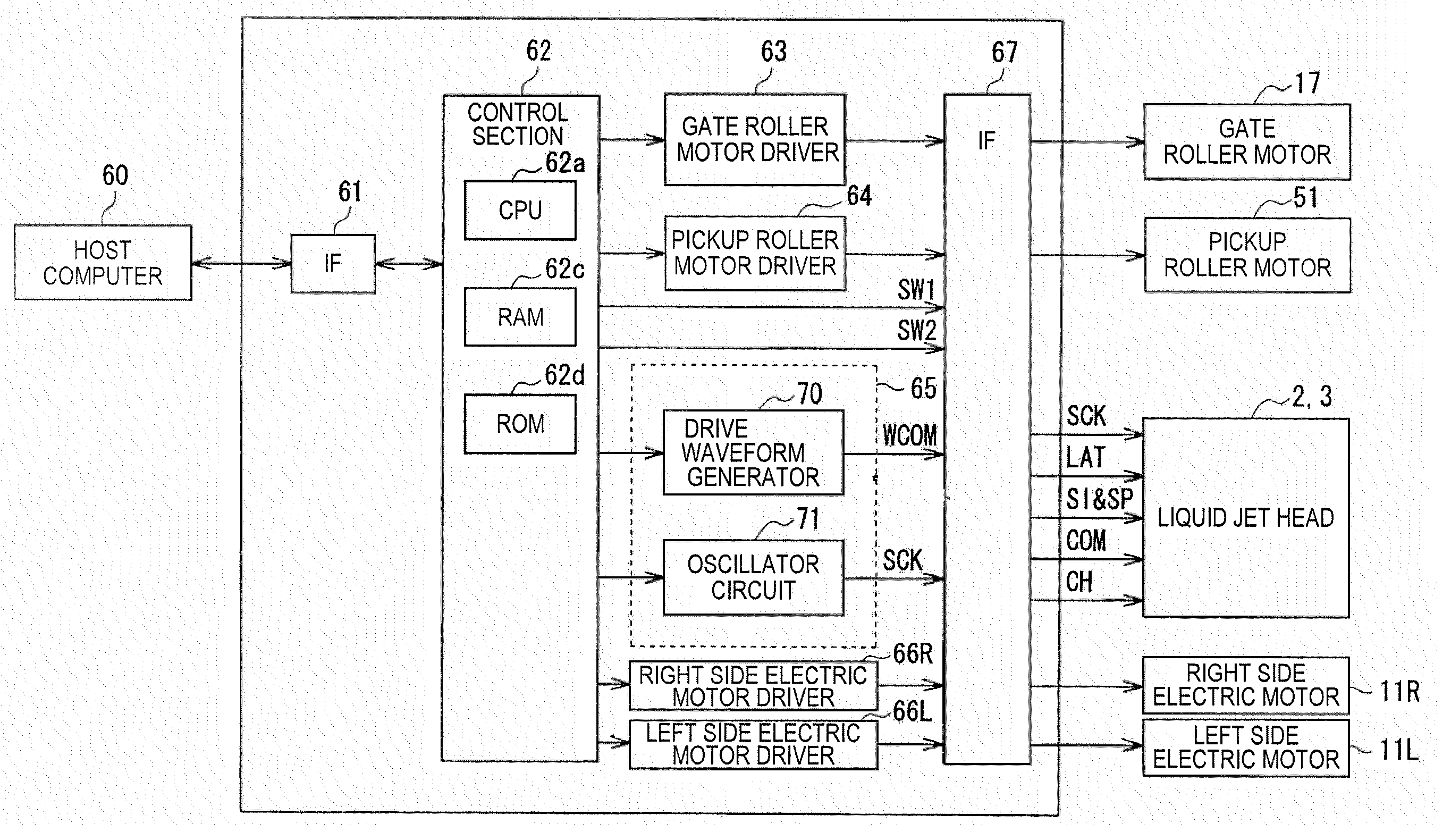
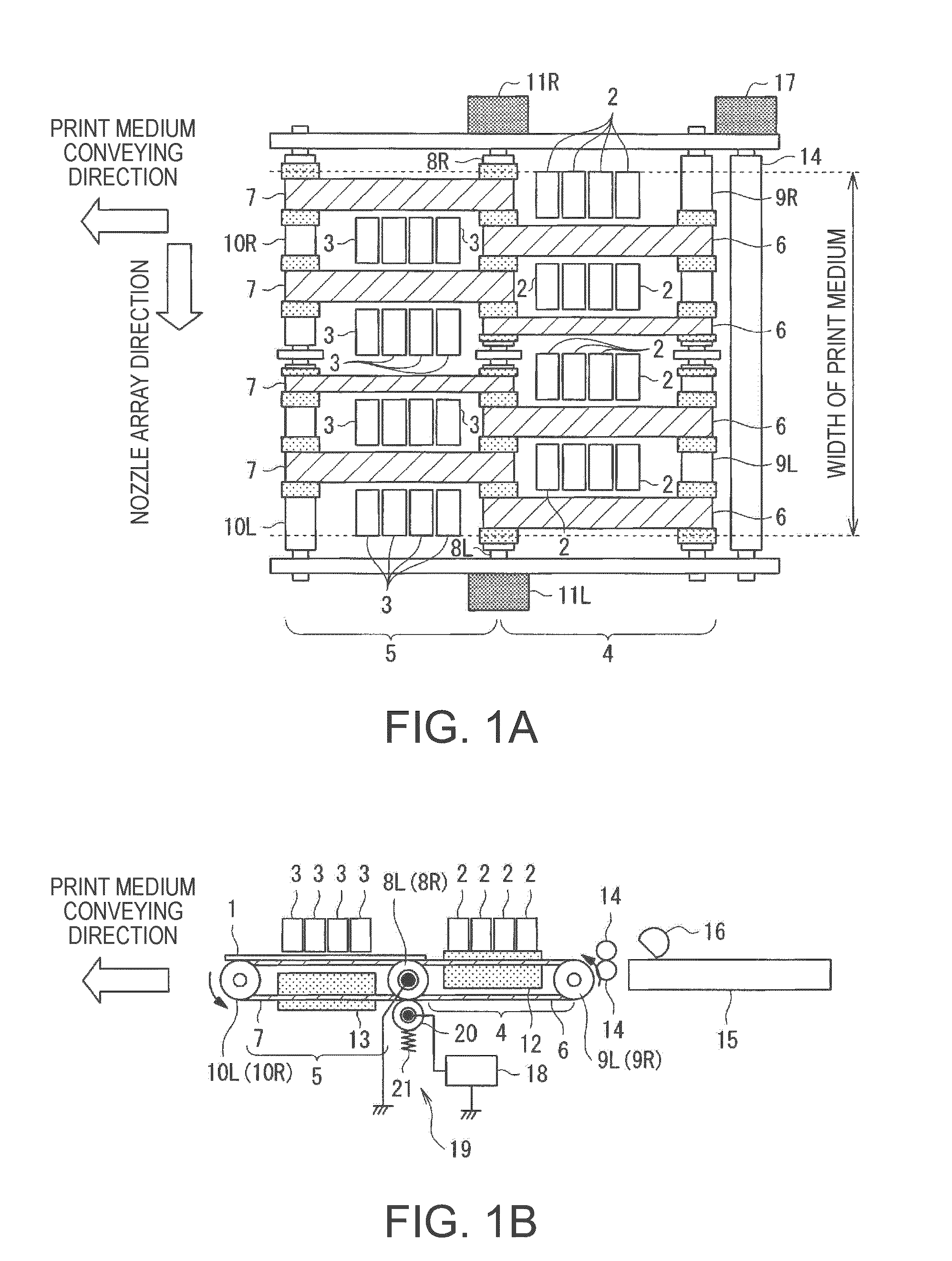
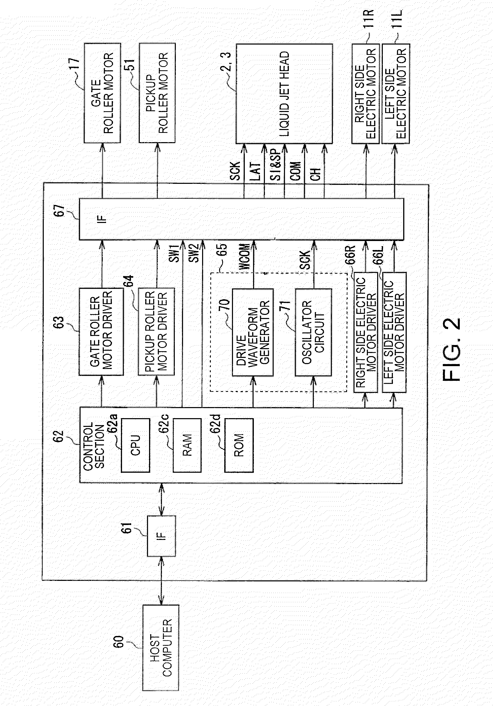
[0033]FIGS. 1A and 1B are schematic configuration views of the print device according to the present embodiment, wherein FIG. 1A is a plan view thereof, and FIG. 1B is a front view thereof. In FIG. 1, in the line head print device, a print medium 1 is conveyed from upper right to lower left of the drawing along the arrow direction, and is printed in a print area in the middle of the conveying path. It should be noted that the liquid jet head of the present embodiment is not disposed integrally in one place, but is disposed separately in two places.

[0034] The reference numeral 2 in the drawing denotes a first liquid jet head disposed on the upstream side in the conveying direction of the print medium 1, the reference numeral 3 denotes a second liquid jet head disposed downstream side...


PUM


Abstract

A liquid jet apparatus includes a plurality of nozzles provided to the liquid jet head, an actuator provided corresponding to each of the nozzles, drive unit that applies a drive signal to the actuator, drive waveform signal generation unit that generates a drive waveform signal providing a reference of a signal for controlling the actuator, modulator unit that pulse-modulates the drive waveform signal generated by the drive waveform signal generation unit, a digital power amplifier for power-amplifying the modulated signal, which is pulse-modulated by the modulator unit, and a low-pass filter provided individually corresponding to the actuator and for supplying the actuator with the power amplified modulated signal power-amplified by the digital power amplifier as a drive signal after smoothing.

Description

BACKGROUND [0001] 1. Technical Field [0002] The present invention relates to a liquid jet device and printing device arranged to print predetermined letters and images by emitting microscopic droplets of liquids from a plurality of nozzles to form the microscopic particles (dots) thereof on a printing medium. [0003] 2. Related Art [0004] An inkjet printer as one of such printing devices, which is generally low-price and easily provides high quality color prints, has widely been spreading not only to offices but also to general users along with the widespread of personal computers or digital cameras. [0005] Further, in recent inkjet printers, printing in fine tone is required. Tone denotes a state of density of each color included in a pixel expressed by a liquid dot, the size of the liquid dot corresponding to the color density of each pixel is called a tone grade, and the number of the tone grades expressed by the liquid dot is called a tone number. The fine tone denotes that the t...

Claims


Application Information

Patent Timeline
Patent Type & Authority Applications(United States)
IPC IPC(8): B41J29/38
CPCB41J29/38
Inventor OSHIMA, ATSUSHITABATA, KUNIOSUZUKI, TOSHIYUKISHINKAWA, OSAMUHATANO, TOMOKI
Owner SEIKO EPSON CORP
Why Eureka
Try Eureka