
Cooling Device for Light Emitting Diode (LED) Module and Method for Fabricating the Same

a cooling device and light-emitting diode technology, which is applied in the direction of semiconductor devices for light sources, electrical apparatus construction details, light and heating apparatuses, etc., can solve the problems of low reliability of chips, high manufacturing cost, and small thermal resistance of the whole module, so as to reduce the thickness of the whole module. , the effect of reducing the thickness of the whole modul

Inactive Publication Date: 2008-01-24
ALTI ELECTRONICS
View PDF6 Cites 34 Cited by
  • Summary
  • Abstract
  • Description
  • Claims
  • Application Information

AI Technical Summary

Benefits of technology

[0013]It is an object of the present invention to provide a cooling device of an LED module in which a thickness competitive power is obtained by reducing the thickness of the whole module, a thermal resistance is small by shortening a final heat releasing path from a heat source, and it is easy to release heat and a method for fabricating the same.
[0014]It is another object of the present invention to provide a cooling device of an LED module in which a manufacturing cost is low since the MC PCB and the thermal pad which are high-priced are substituted, the weight of the whole module is light, and the adhering flatness of the PCB is excellent and a method for fabricating the same.
[0015]It is yet another object of the present invention to provide a cooling device of an LED module in which processing efficiency and productivity are improved and the manufacturing process is simplified since the LED package is mounted without using the bending process of the lead frame of the LED, and deterioration of the chip is prevented since the heat releasing substrate does not contact the PCB during the high temperature reflow process and a method for fabricating the same.

Problems solved by technology

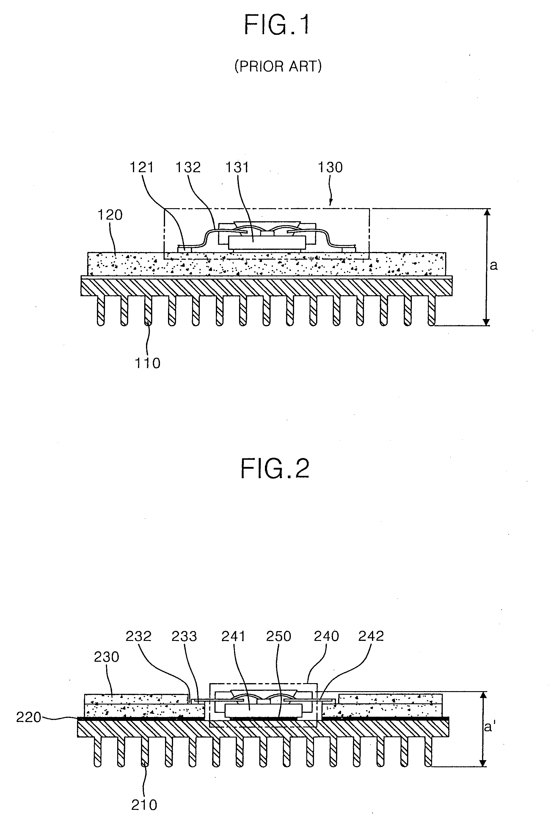
However, the cooling device of the LED module of FIG. 1 uses the MC PCB and thermal pad which are high-priced, and so its manufacturing cost is high.
In particular, when the LED module is used as the backlight unit of the LCD device, there is a problem for minimizing a distance between a light source and an optical sheet.
In addition, in case of a chip on board (“COB”) type in which an LED chip is attached directly to an LED, it is not easy to repair a single-unit LED package, and since the MC PCB directly contacts the heat slug, conduction of heat to the chip is accelerated when the LED is solder-mounted on the PCB, whereby reliability of the chip is low.

Method used


Image

  • Cooling Device for Light Emitting Diode (LED) Module and Method for Fabricating the Same
  • Cooling Device for Light Emitting Diode (LED) Module and Method for Fabricating the Same
  • Cooling Device for Light Emitting Diode (LED) Module and Method for Fabricating the Same

Examples


Embodiment Construction

[0027]Reference will now be made in detail to the embodiments of the present invention, examples of which are illustrated in the accompanying drawings, wherein like reference numerals refer to the like elements throughout. The embodiments are described below in order to explain the present invention by referring to the figures.

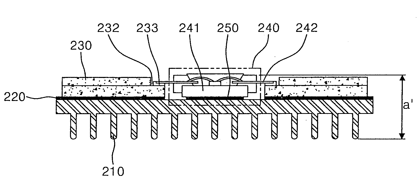
[0028]FIG. 2 is a cross-sectional view illustrating a cooling device of an LED module according to one exemplary embodiment of the present invention.

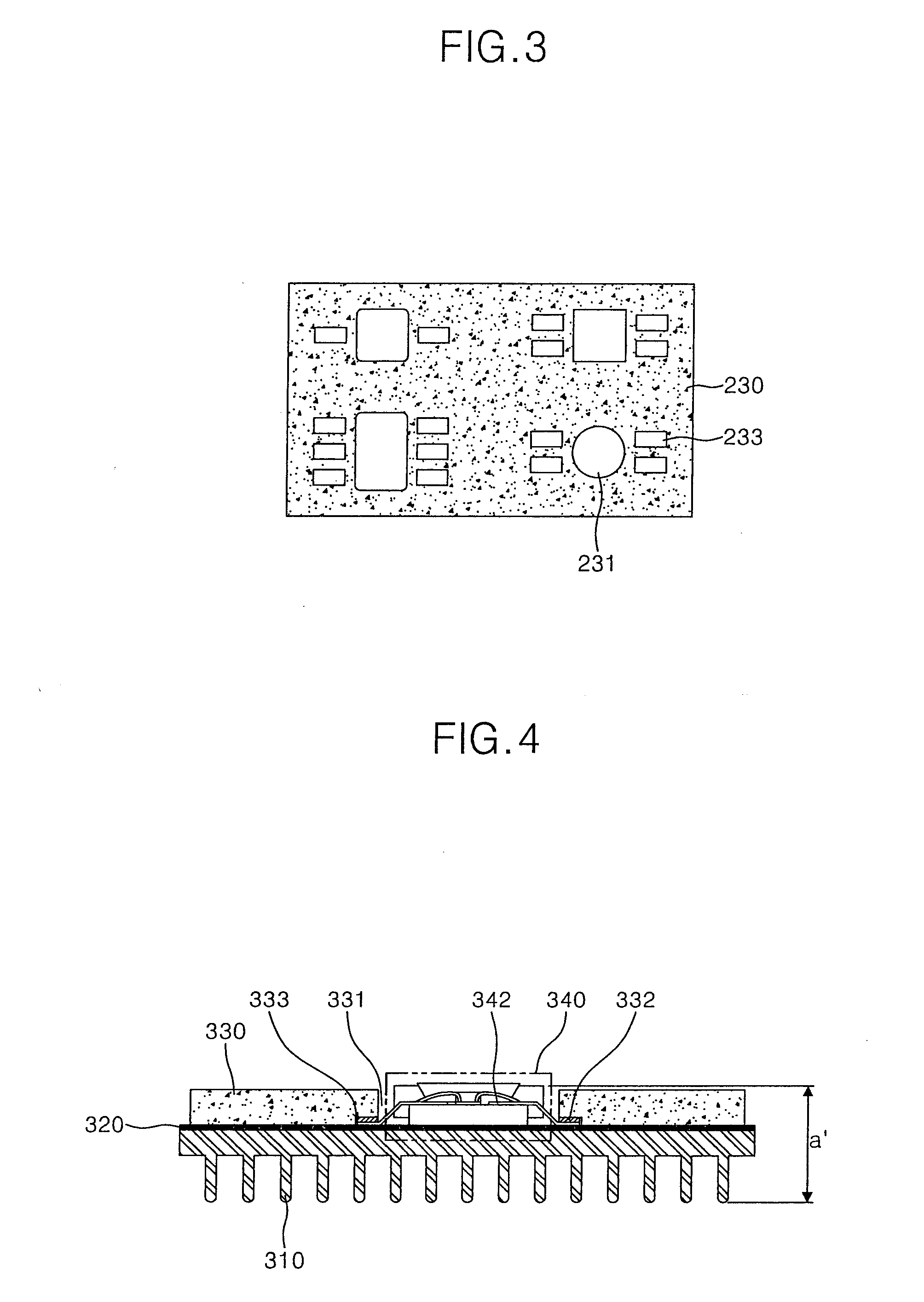
[0029]Referring to FIG. 2, the cooling device of the LED module comprises a heat releasing substrate 210 for releasing heat generated from an LED, a PCB substrate 230 which is mounted on the heat releasing substrate 210 and includes an electrode pad 233 and a penetrated portion 231 in which an LED package 240 is mounted, and the LED package 240 mounted on the heat releasing substrate 210 through the penetrated portion 231 of the PCB 230.

[0030]The LED package 240 comprises an LED chip for emitting light, a lead fra...


PUM

PropertyMeasurementUnit
temperatureaaaaaaaaaa
heat resistantaaaaaaaaaa

Abstract

A cooling device of a light emitting diode module and a method for fabricating the same are disclosed. According to the cooling device for a light emitting diode module of the present invention, the thickness of the whole module is reduced, a thermal resistance is small since a final heat-releasing path from a heat source is shortened, it is easy to release heat, and processing efficiency is high and manufacturing cost is low because a bending process of a lead frame is removed.

Description

CROSS-REFERENCE TO RELATED APPLICATION[0001]This application claims priority to and the benefit of Korean Patent Application No. 10-2006-67250, filed Jul. 19, 2006, the disclosure of which is incorporated herein by reference in its entirety.BACKGROUND OF THE INVENTION[0002]1. Field of the Invention[0003]The present invention relates to a cooling device for a light emitting diode (“LED”) and method for fabricating the same and, more particularly, to a cooling device for an LED module in which the thickness of the whole module is reduced, a thermal resistance is small since a final heat-releasing path from a heat source is shortened, it is easy to release heat, and processing efficiency is high and manufacturing cost is low because a bending process of a lead frame is removed and method for fabricating the same.[0004]2. Description of the Related Art[0005]An LED emits light when a voltage is applied thereto and is usually employed in a lighting device or a backlight unit of a liquid c...

Claims


Application Information

Patent Timeline
Patent Type & Authority Applications(United States)
IPC IPC(8): H05K7/20H05K3/00H01L33/64H01L33/62
CPCF21V29/004F21Y2101/02H05K1/021H05K1/182H05K3/0061Y10T29/49124H05K2201/10106H01L2224/48247H01L2224/48091H01L2924/00014F21Y2115/10F21V29/508
Inventor KIM, DONG SOO
Owner ALTI ELECTRONICS
Learn More