Low-profile backlight with flexible light guide

a backlight and flexible technology, applied in the direction of measurement apparatus components, lighting and heating apparatus, light fastenings, etc., can solve the problems of backlighting technology b>10/b>, affecting the size and functionality of the device in which it is used, and creating poor brightness uniformity. , to achieve the effect of reducing the size of the devi

Inactive Publication Date: 2008-01-24
AVAGO TECH INT SALES PTE LTD
View PDF12 Cites 17 Cited by
  • Summary
  • Abstract
  • Description
  • Claims
  • Application Information

AI Technical Summary

Benefits of technology

[0006]A backlighting apparatus is described. One embodiment of the backlighting apparatus includes a flexible light guide, a light source, and a housing. The light source is disposed adjacent to a transmission interface of the flexible light guide to illuminate the flexible light guide. The housing at least partially encloses the flexible light guide and the light source. A surface area of the flexible light guide is visible through the housing. By using a flexible light guide to backlight the device, the size of the device is reduced compared to conventional devices. Alternatively, the device may accommodate additional components. Other advantages also may be achieved.

Problems solved by technology

While current keypad backlighting technologies enhance the visible recognition of individual keys, the current keypad backlighting technologies negatively impact the size and functionality of the devices in which they are used.
Unfortunately, this conventional backlighting system 10 has a disadvantage of creating poor brightness uniformity due to noticeable hot spots from the LEDs 12.
Unfortunately, this conventional backlighting system 30 also has a disadvantage of hot spots from the holes 34 in the light guide panel 14 to accommodate the keypad plungers 22.
The holes 34 result in localized hot spots and deteriorate the brightness uniformity performance of the light guide panel.
However, the rectifier circuitry in EL backlighting systems generates noise which negatively interferes with other electronic circuitry within the backlit device.

Method used


Image

  • Low-profile backlight with flexible light guide
  • Low-profile backlight with flexible light guide
  • Low-profile backlight with flexible light guide

Examples


Embodiment Construction

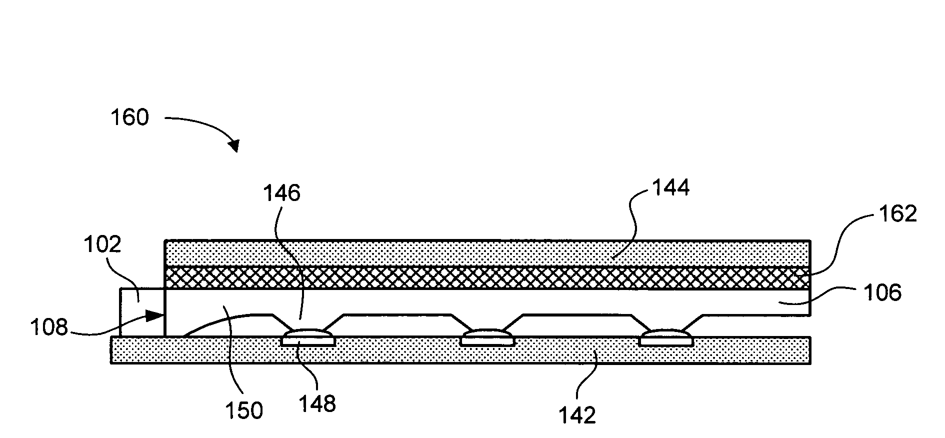
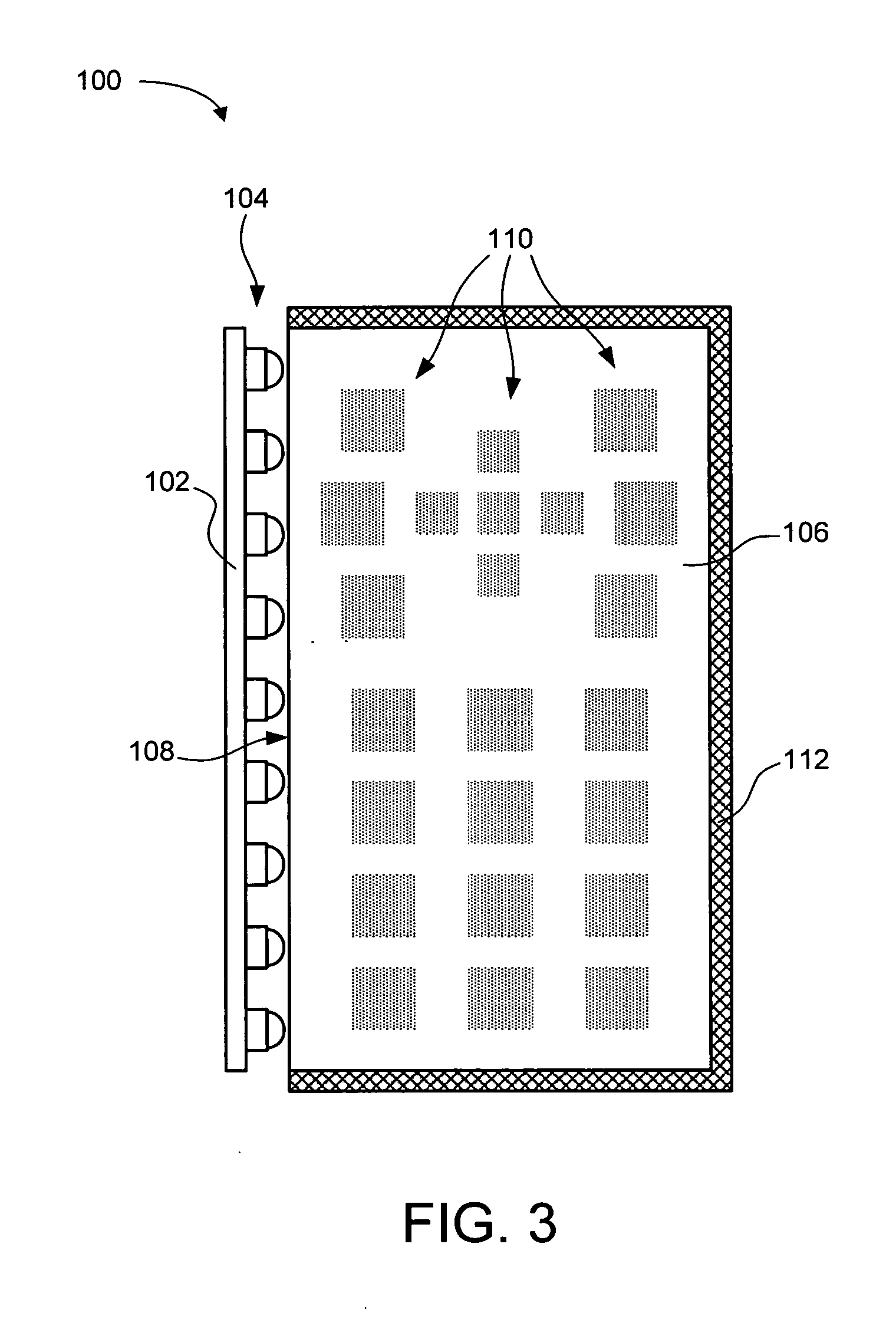
[0019]FIG. 3 depicts an embodiment of a backlighting system 100 using a flexible light guide 106. The depicted backlighting system 100 is representative of many different types of electronic devices which use or might benefit from a backlit keypad, backlit buttons, or other backlit components. One exemplary electronic device is a mobile telephone having backlit buttons. Another exemplary electronic device is a personal digital assistant (PDA) having a backlit keypad. Other types of electronic devices also my employ the flexible light guide 106 described herein.

[0020]The illustrated backlighting system 100 includes a light source 102 to illuminate the flexible light guide 106. In one embodiment, the light source 102 includes multiple light emitting diodes (LEDs) 104. The LEDs 104 may be surface mount technology (SMT) LEDs or another type of LED. Alternatively, the light source 102 may be another type of light source other than LEDs 104. In the depicted embodiment, the LEDs 104 are di...


PUM


Abstract

Backlighting methods and apparatuses to backlight a device. The backlighting apparatus includes a flexible light guide, a light source, and a housing. The light source is disposed adjacent to a transmission interface of the flexible light guide to illuminate the flexible light guide. The housing at least partially encloses the flexible light guide and the light source. A surface area of the flexible light guide is visible through the housing. By using a flexible light guide to backlight the device, the size of the device is reduced compared to conventional devices. Alternatively, the device may accommodate additional components. Other advantages also may be achieved.

Description

BACKGROUND OF THE INVENTION[0001]Keypad backlighting is currently used in many electronic devices such as mobile phones and personal digital assistants. While current keypad backlighting technologies enhance the visible recognition of individual keys, the current keypad backlighting technologies negatively impact the size and functionality of the devices in which they are used.[0002]FIG. 1 depicts a cross-sectional view of a conventional backlighting system 10 using top-emitting light emitting diodes (LEDs) 12. Specifically, the LEDs 12 are wide-angle, top-emitting, component LEDs 12. The LEDs 12 illuminate a stiff light guide panel 14. The LEDs 12 and light guide panel 14 are disposed within a housing having a top plate 16 and a bottom plate 18. Typically, the light guide panel 14 is punched with holes so that keypad plungers 22 can extend through the light guide panel 14. The keypad plungers 22 are coupled to a plunger layer 20 that is a low optical grade material. When a user pus...

Claims


Application Information

Patent Timeline
Patent Type & Authority Applications(United States)
IPC IPC(8): F21V23/04G01D11/28F21V8/00
CPCG01D11/28G02B6/0036G02B6/0055H04M1/22G02B6/0068G02B6/0081G02B6/006Y10S362/80
Inventor NG, FOOK CHUINKO, CHOON GUANLEE, SIAN TATT
Owner AVAGO TECH INT SALES PTE LTD
Why Eureka
Try Eureka