
Method and apparatus for controlling x-ray machine to irradiate a narrowed portion

Inactive Publication Date: 2008-01-24
TECO ELECTRIC AND MACHINERY
View PDF9 Cites 7 Cited by
  • Summary
  • Abstract
  • Description
  • Claims
  • Application Information

AI Technical Summary

Benefits of technology

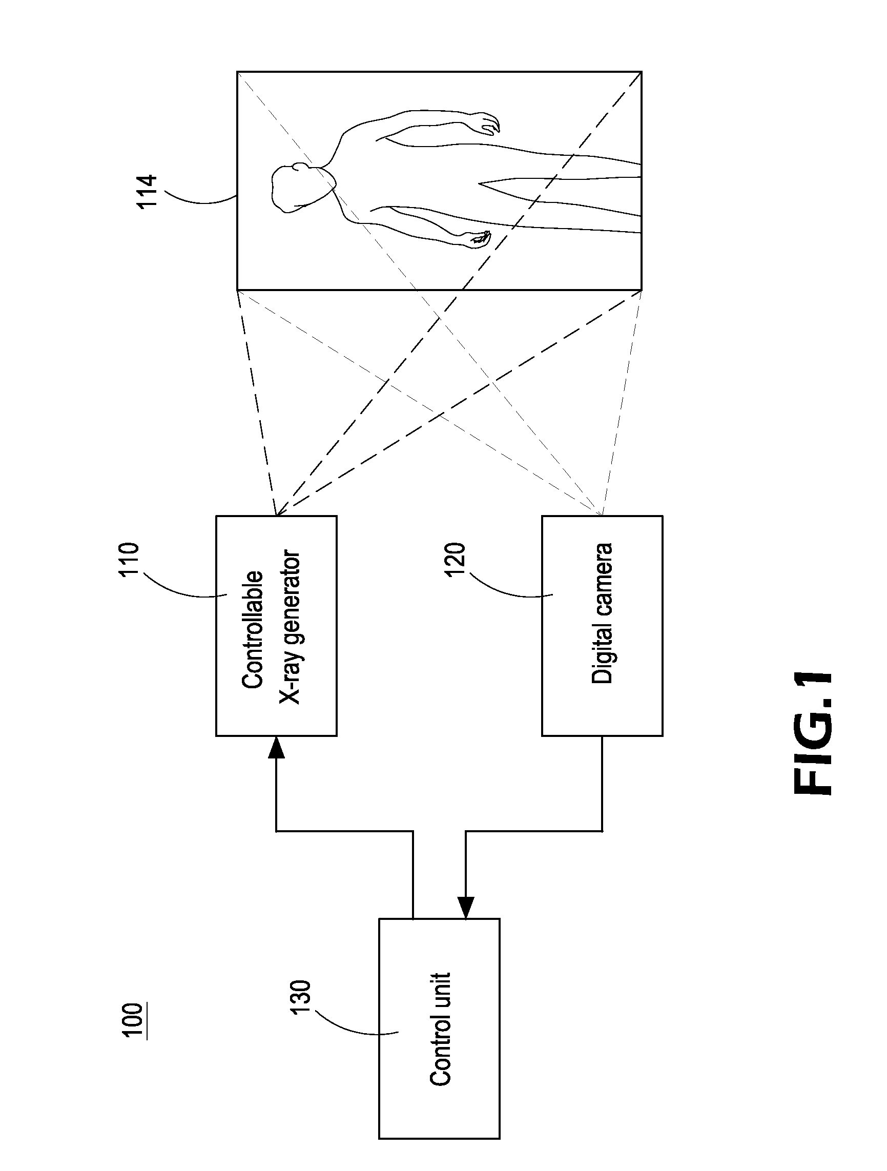
[0009]To achieve the foregoing objective, the present invention provides a controllable X-ray machine comprising a controllable X-ray generator, a digital camera and a control unit. The control unit electrically connects the controllable X-ray generator and the digital camera. The controllable X-ray generator can be controlled to adjustably irradiate a narrowed object portion within a maximum irradiation range thereof. The digital camera is arranged correspondingly to the controllable X-ray generator to shoot a digital visible-light image which is the sa

Problems solved by technology

Unlike visible lights, X-rays are radioactive and hazardous to human.
For example, X-rays are also used in the inspection of electronic apparatuses, and may damage the electric components of the electronic apparatuses.
However, the conventional X-ray machine can only be used for providing a predetermined and fixed irradiating range and can not be adjusted according to actual situations to narrow down.

Method used


Image

  • Method and apparatus for controlling x-ray machine to irradiate a narrowed portion
  • Method and apparatus for controlling x-ray machine to irradiate a narrowed portion
  • Method and apparatus for controlling x-ray machine to irradiate a narrowed portion

Examples


Embodiment Construction

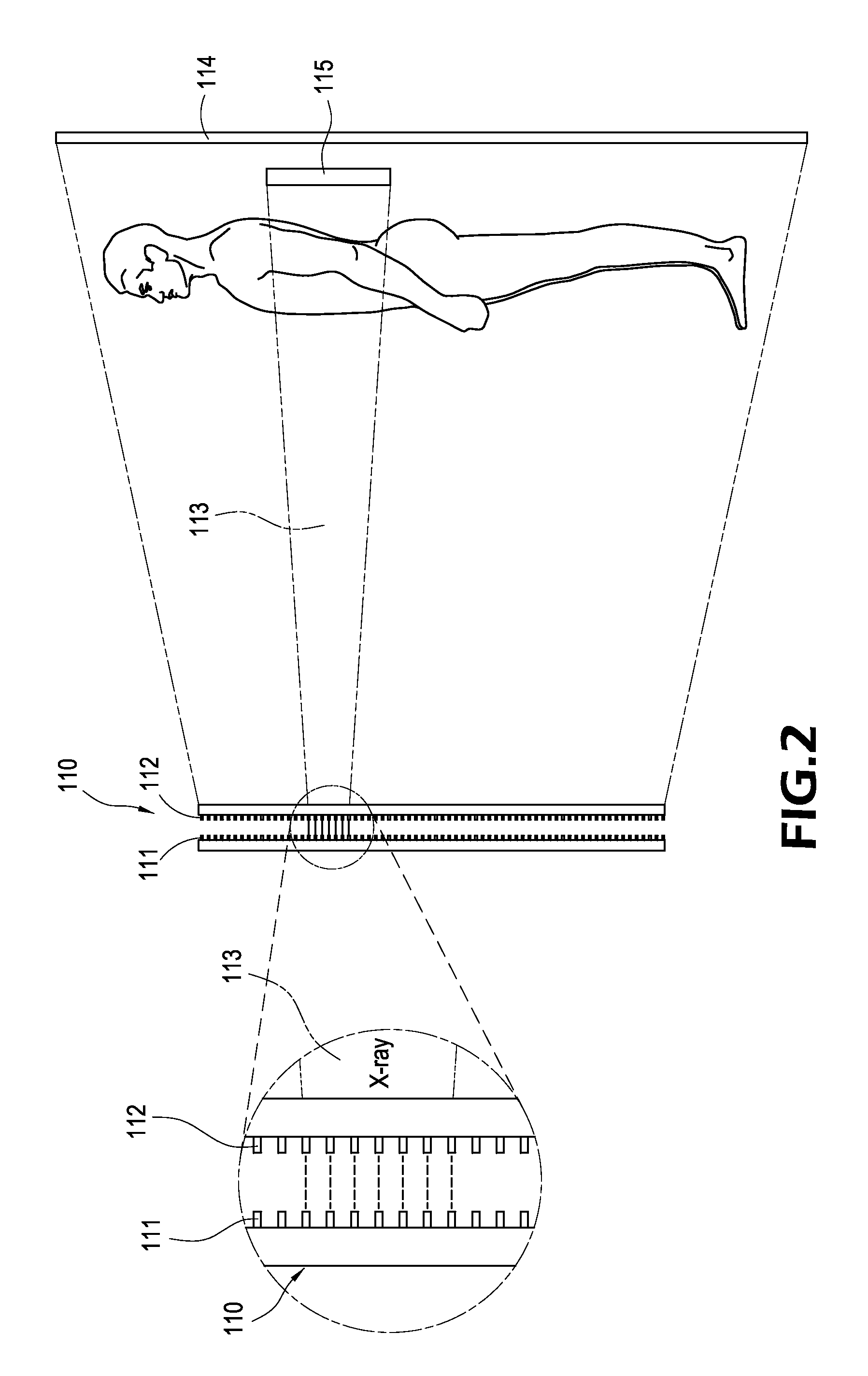
[0015]FIG. 1 shows a block diagram of the controllable X-ray machine 100 for irradiating a narrowed portion according to the present invention. The controllable X-ray machine 100 includes a controllable X-ray generator 110, a digital camera 120 and a control unit 130. The X-ray generator 110 and the digital camera 120 are electrically connected to the control unit 130. The X-ray generator 110 is a cold cathode field emission device essentially including a plurality of coupling anodes and cathodes. As shown in FIG. 2, each cathode 111 aligns a corresponding anode 112 and can be controlled individually. Each of the cathodes 111 individually emits e-beams to the corresponding anode 112 when an electric field is applied between a couple of a specific anode 112 and cathode 111. Then the anodes 112 which are collided by the e-beams from the cathodes 111 will emit X-rays 113 outward. A maximum irradiation range 114 of the X-ray generator 110 will exist while all of the anodes 112 are emitt...


PUM


Abstract

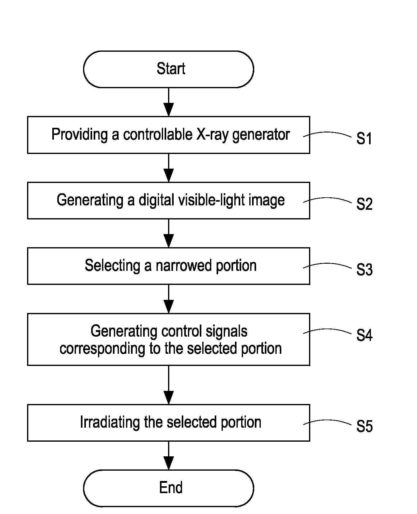
An X-ray machine being able to irradiate a narrowed portion within a maximum irradiation range through a control to the electrodes of an X-ray generator is provided. The X-ray machine includes a controllable X-ray generator, a digital camera and a control unit. The digital camera produces a digital visible-light image the same as the maximum irradiation range of the X-ray generator. A narrowed image portion within the digital image can be selected by the control unit. The control unit generates control signals corresponding to the selected image portion. The X-ray generator emits X-rays onto an object portion corresponding to the selected image portion based on the control signals.

Description

[0001]This application is a continuation-in-part of U.S. patent application Ser. No. 11 / 459,512 filed Jul. 24, 2006.BACKGROUND OF THE INVENTION[0002]1. Technical Field[0003]The present invention relates to an X-ray machine, and more particularly to an X-ray machine with narrowing irradiation.[0004]2. Description of Prior Art[0005]X-rays are a form of ionizing radiation. An X-ray machine emits radioactive rays to produce an image of an object for visualizing something located under the surface of the object, and thus X-rays are primarily used for diagnostic radiography and crystallography. Nowadays, X-ray machines have become one of the most indispensable medical instruments. X-ray machines are often used for irradiating a specific portion of a patient for detecting fracture, cancers or inserted foreign matters in human bodies. Unlike visible lights, X-rays are radioactive and hazardous to human. Therefore, the range of the patient that is irradiated by the X-ray should be minimized ...

Claims


Application Information

Patent Timeline
IPC IPC(8): H05G1/64
CPCA61B5/0059A61B6/542A61B6/00
Inventor CHENG, KUEI-WENJENG, JENG-YWANCHAN, TE-FONG
Owner TECO ELECTRIC AND MACHINERY
Learn More