

Long cavity single-mode laser diode
a laser diode and long cavity technology, applied in semiconductor lasers, instruments, optical elements, etc., can solve the problems of low modulation speed, poor single-mode stability, large size, etc., and achieve the effect of improving the stability of single-mode considerably
- Summary
- Abstract
- Description
- Claims
- Application Information
AI Technical Summary
Benefits of technology
Problems solved by technology
Method used
Image

Examples
Embodiment Construction
[0050]The present invention will now be described more fully with reference to the accompanying drawings, in which exemplary embodiments of the invention are shown.
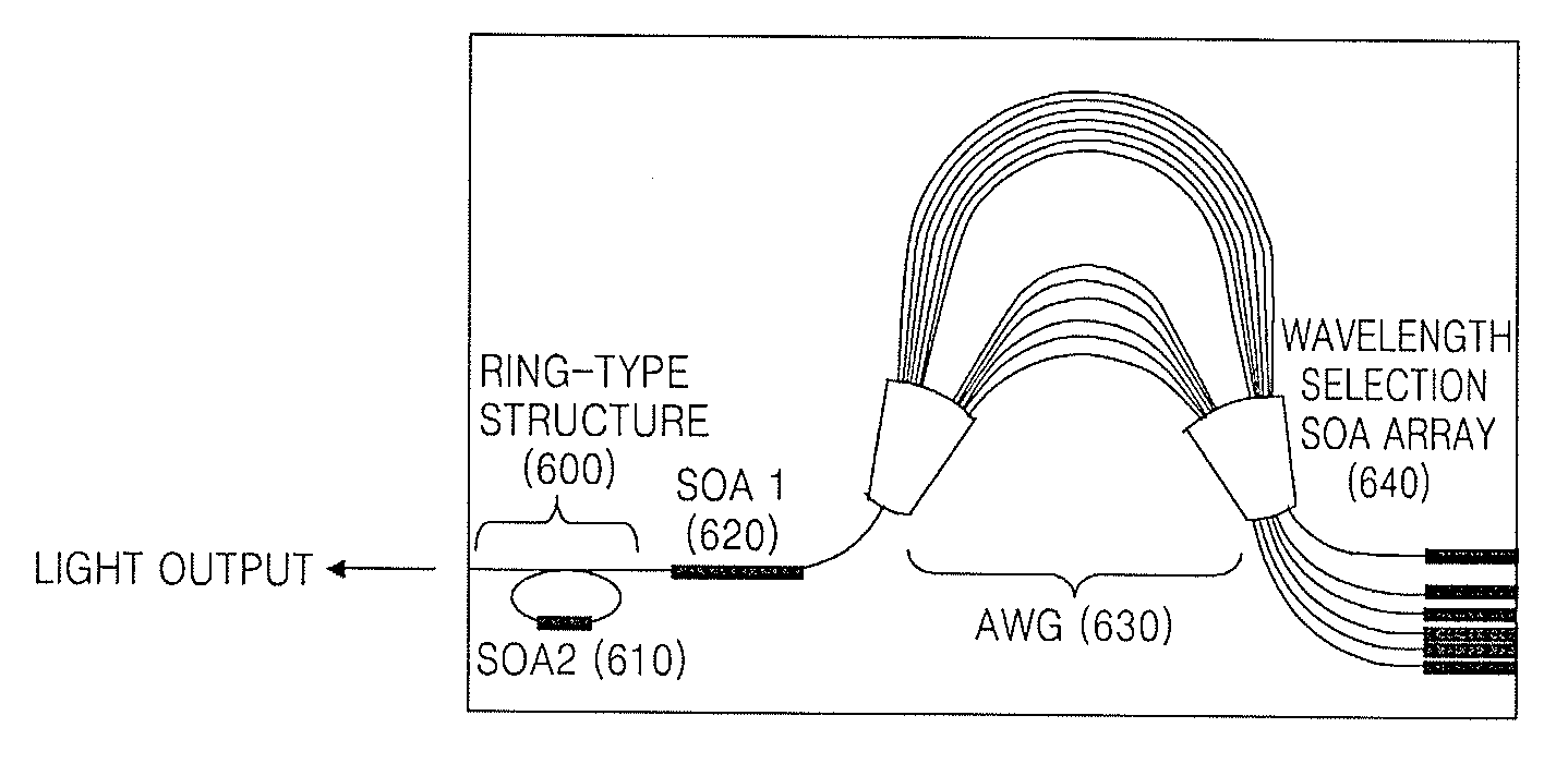
[0051]FIG. 6 is a schematic view of an array waveguide grating (AWG)-based laser in which a ring-type structure 600 having an optical amplifier is integrated, according to an embodiment of the present invention. FIG. 7A illustrates a ring-type structure without an optical amplifier, and FIG. 7B is a graph illustrating an operating characteristics of the ring-type structure of FIG. 7A.
[0052]Referring to FIG. 6, the ring-type structure 600 is integrated in a conventional long cavity single-mode semiconductor. The ring-type structure 600 includes an additional optical amplifier (SOA2) 610 in a ring-type waveguide.
[0053]The ring-type filter is usually used as a band rejection filter (Notch filter) as described in Reference 13 (“D. G. Rabus et al, “MMI-coupled ring resonators in GaInAsP—InP,” IEEE Photon. Technol. Lett., vol. ...
PUM
 Abstract
Description
Claims
Application Information