Method and apparatus for steam hydro-gasification in a fluidized bed reactor

a fluidized bed reactor and hydrogasification technology, which is applied in the direction of combustible gas purification/modification, lighting and heating apparatus, furnaces, etc., can solve the problems of reducing the catalyst efficiency, serious environmental pollution, and a major dependence on petroleum, so as to promote heat and mass transfer, improve the effect of economics and good mixing

Inactive Publication Date: 2008-01-24
RGT UNIV OF CALIFORNIA
View PDF25 Cites 34 Cited by
  • Summary
  • Abstract
  • Description
  • Claims
  • Application Information

AI Technical Summary

Benefits of technology

[0016]Notwithstanding the above drawbacks, the present inventors realized that feedstocks used in hydro-gasification reactions, such as coal and biomass, can be sufficiently reactive to operate at the lower temperatures of fluidized bed processes. This invention provides an improved, economical alternative method of conducting hydro-gasification, by operat

Problems solved by technology

Since the resources for the production of petroleum-based fuels are being depleted, dependency on petroleum will become a major problem unless non-petroleum alternative fuels, in particular clean-burning synthetic diesel fuels, are developed.
Moreover, normal combustion of petroleum-based fuels in conventional engines can cause serious environmental pollution unless strict methods of exhaust emission control are used.
Such a process allows for the application of current state-of-art engine exhaust after-treatment methods for NOx reduction, removal of toxic particulates present in diesel engine exhaust, and the reduction of normal combustion product pollutants, currently accomplished by catalysts that are poisoned quickly by any sulfur present, as is the case in ordinary stocks of petroleum derived diesel fuel, reducing the catalyst efficiency.
These waste sources of carbonaceous material are not the only sources available.
Unfortunately, open burning of biomass waste to obtain energy and heat is not a clean and efficient method to utilize the calorific value.
A number of processes exist to convert coal, biomass, and other carbonaceous materials to clean-burning transportation fuels, but they tend to be too expensive to compete on the market with petroleum-based fuels, or they produce volatile fuels, such as methanol and ethanol that have vapor pressure values too high for use in high pollution areas, such as the Southern California air-basin, wi

Method used


Image

  • Method and apparatus for steam hydro-gasification in a fluidized bed reactor
  • Method and apparatus for steam hydro-gasification in a fluidized bed reactor
  • Method and apparatus for steam hydro-gasification in a fluidized bed reactor

Examples


Embodiment Construction

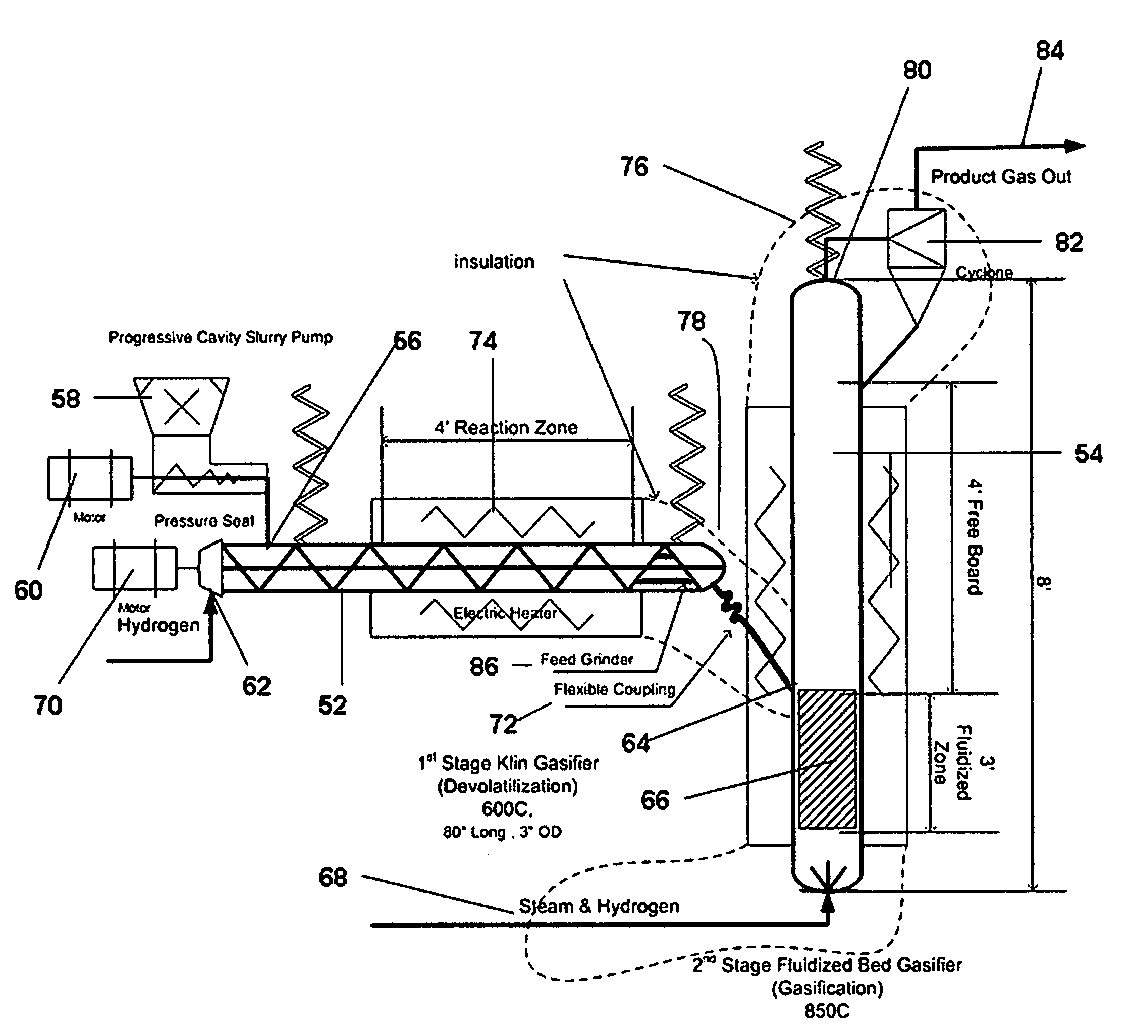
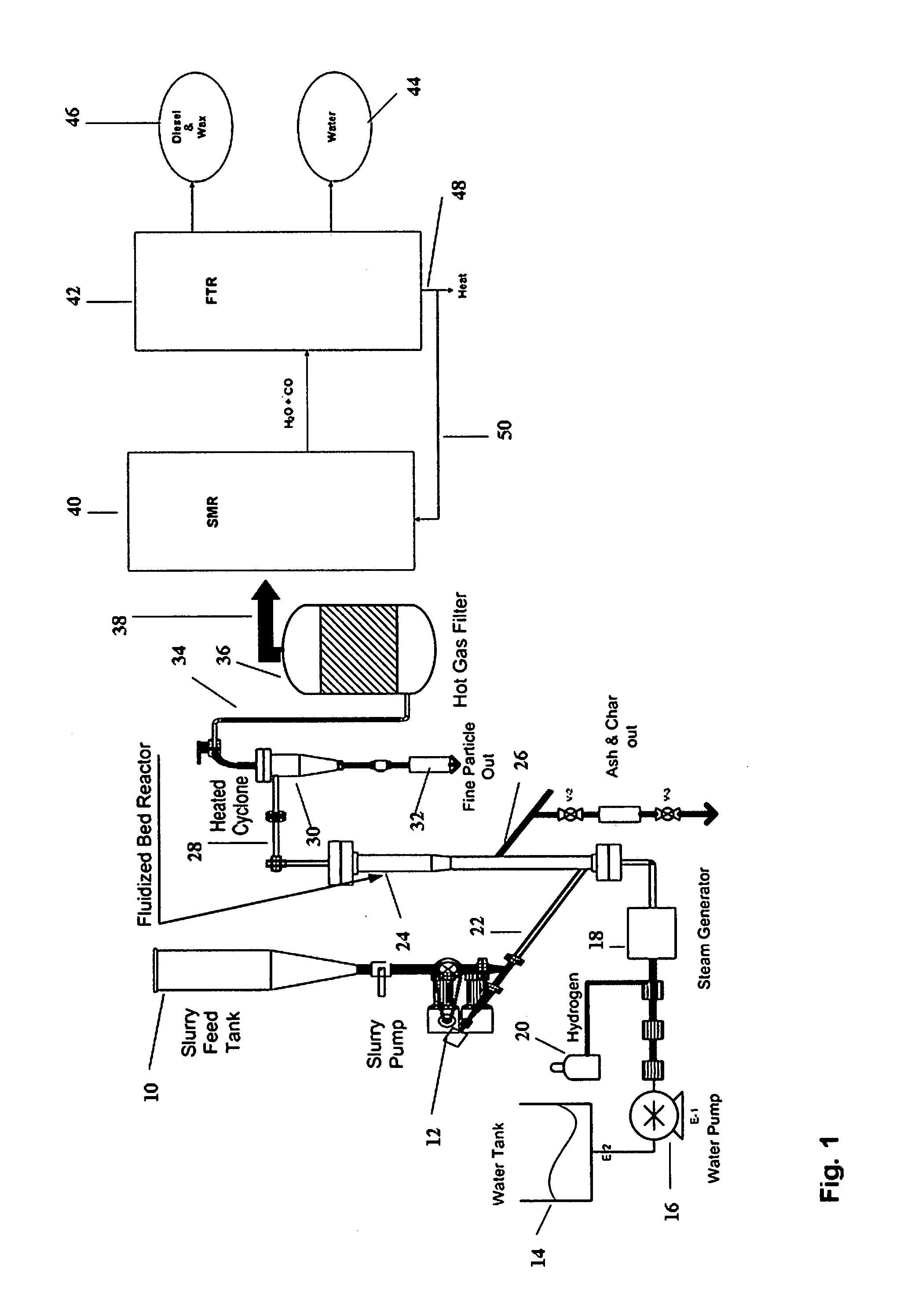
[0027]Referring to FIG. 1, Apparatus is shown in accordance with a first embodiment of the invention for a process for converting carbonaceous material such as municipal waste, biomass, wood, coal, or a natural or synthetic polymer to a methane and carbon monoxide rich gas. The carbonaceous material in the form of a slurry is loaded into a slurry feed tank 10 and gravity fed to a slurry pump 12. In this embodiment, water from a water tank 14 is fed by a water pump 16 to a steam generator 18. Simultaneously, hydrogen is fed to the steam generator 18, which can be from a tank 20 of hydrogen, from an internal source such as the output from a downstream steam methane reformer (as will be described below), or from both. The output of the slurry pump 12 is fed through line 22 to the bottom of a fluidized bed reactor 24 while the output from the steam generator 18 is fed through line 25 to the fluidized bed reactor 24 at a point below the slurry of carbonaceous material.

[0028]In another em...


PUM

PropertyMeasurementUnit
Temperatureaaaaaaaaaa

Abstract

A method and apparatus for converting carbonaceous material to a stream of methane and carbon monoxide rich gas by heating the carbonaceous material in a fluidized bed reactor using hydrogen, as fluidizing medium, and using steam, under reducing conditions at a temperature and pressure sufficient to generate a stream of methane and carbon monoxide rich gas but at a temperature low enough and/or at a pressure high enough to enable the carbonaceous material to be fluidized by the hydrogen. In particular embodiments, the carbonaceous material is fed as a slurry feed, along with hydrogen, to a kiln type reactor before being fed to the fluidized bed reactor. Apparatus is provided comprising a kiln type reactor, a slurry pump connected to an input of the kiln type reactor, means for connecting a source of hydrogen to an input of the kiln type reactor; a fluidized bed reactor connected to receive output of the kiln type reactor for processing at a fluidizing zone, and a source of steam and a source of hydrogen connected to the fluidized bed reactor below the fluidizing zone. Optionally, a grinder can be provided in the kiln type reactor.

Description

CROSS-REFERENCE TO RELATED APPLICATIONS[0001]This application is a continuation-in-part of, and claims the benefit of, patent application Ser. No. 11 / 489,353, filed Jul. 18, 2006.FIELD OF THE INVENTION[0002]The field of the invention is the synthesis of transportation fuel from carbonaceous feed stocks.BACKGROUND OF THE INVENTION[0003]There is a need to identify new sources of chemical energy and methods for its conversion into alternative transportation fuels, driven by many concerns including environmental, health, safety issues, and the inevitable future scarcity of petroleum-based fuel supplies. The number of internal combustion engine fueled vehicles worldwide continues to grow, particularly in the midrange of developing countries. The worldwide vehicle population outside the U.S., which mainly uses diesel fuel, is growing faster than inside the U.S. This situation may change as more fuel-efficient vehicles, using hybrid and / or diesel engine technologies, are introduced to redu...

Claims


Application Information

Patent Timeline
IPC IPC(8): C07C27/06F27B15/00
CPCC01B3/34C10K3/00C01B2203/062C01B2203/0838C01B2203/1241C01B2203/148C01B2203/84C10G2/32C10J3/005C10J3/463C10J3/503C10J2300/093C10J2300/0966C10J2300/0973C10J2300/1659Y02E20/18Y02E50/32C01B2203/0233Y02E50/30
Inventor NORBECK, JOSEPH M.PARK, CHAN SEUNGSINGH, SURINDER P.
Owner RGT UNIV OF CALIFORNIA
Why Eureka
Try Eureka