Expandable spinal fusion cage

a fusion cage and expandable technology, applied in the field of expandable spinal fusion cages, can solve the problems of increasing the risk of injury to the superior nerve root and the medially located thecal sack, and the surgeon's difficulty in placing and orienting implants,

Inactive Publication Date: 2008-01-24
LANX INC
View PDF31 Cites 332 Cited by
  • Summary
  • Abstract
  • Description
  • Claims
  • Application Information

AI Technical Summary

Benefits of technology

[0008]The foregoing and other features, utilities and advantages of the invention will be apparent from the following more particular description of a preferred embodiment of the invention as illustrated in the accompanying drawings.

Problems solved by technology

The larger the implant, the more difficult it is for the surgeon to place and orient the implant.
Moreover, larger implants increase the risk of injury to the superior nerve root and the medially located thecal sack.

Method used


Image

  • Expandable spinal fusion cage
  • Expandable spinal fusion cage
  • Expandable spinal fusion cage

Examples


Embodiment Construction

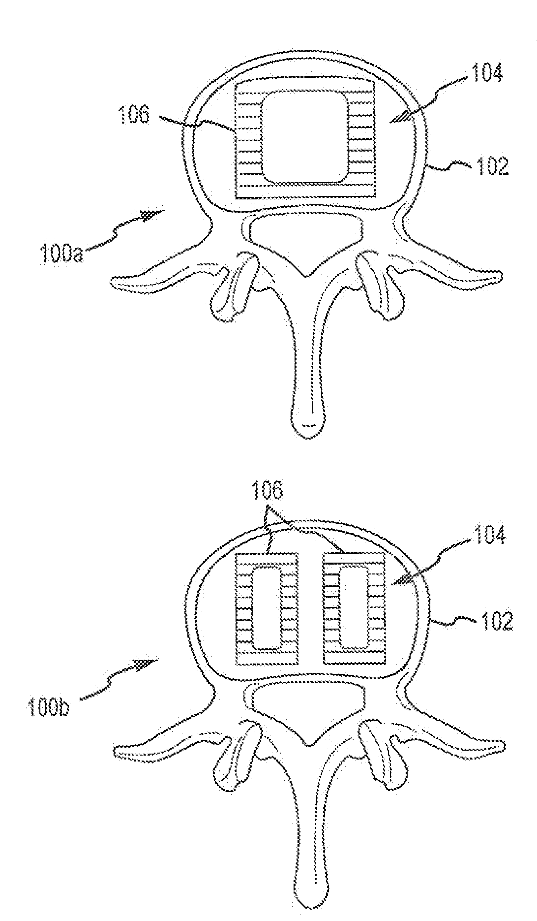
[0018]The present invention will now be described with reference to the figures. Referring first to FIG. 1, an axial view of spinal segments 100a and 100b is shown. Spinal segment includes inferior vertebral body 102, superior vertebral body (not specifically shown, but substantially identical to inferior vertebral body 102), and intervertebral disc space 104. Intervertebral disc space 104 is typically occupied by an intervertebral disc comprising a disc annulus and disc nucleus. To fuse inferior vertebral body 102 and the superior vertebral body, the intervertebral disc may be fully or partially removed, but is shown as fully removed for convenience. Occupying intervertebral disc space 104 is at least one expandable spinal fusion device 106. Depending on the surgical procedure, such as an anterior or posterior approach, and the discs to be fused, one or more devices 106 may be used by the surgeon. As shown in segment 100a, a single device 106 is used. Spinal segment 100b uses two d...


PUM


Abstract

An expandable spinal fusion device is provided. The expandable device comprises a first part slidingly coupled to a second part. An removable expandable member extends between the first part and the second part and is coupled to a rotating operator such that rotating the operator causes the first part and the second part to move away from each other and distract vertebral bodies. A spacer or clip is used to lock the first part in relation to the second part to allow bone growth the fuse the vertebral bodies.

Description

RELATED APPLICATIONS AND CLAIM OF PRIORITY[0001]The present application is a continuation-in-part of U.S. patent application Ser. No. 11 / 456,038, titled EXPANDABLE SPINAL FUSION CAGE, which relates to U.S. Provisional Patent Application Ser. No. 60 / 456,590, filed Mar. 21, 2003, titled Expandable Spinal Fusion Device, which application is expired, the disclosure of which is incorporated herein by reference as if set out in full.FIELD OF THE INVENTION[0002]The present invention relates to spinal corrective surgery and, more particularly to an expandable spinal fusion cage to facilitate fusing a spinal segment into a solid bone mass.BACKGROUND OF THE INVENTION[0003]The vertebrae of the human spine are arranged in a column with one vertebra on top of the next. Between each vertebra exists an intervertebral disc that transmits force between adjacent vertebrae and provides a cushion between the adjacent vertebrae.[0004]Sometimes, back pain is caused by degeneration or other deformity of t...

Claims


Application Information

Patent Timeline
Patent Type & Authority Applications(United States)
IPC IPC(8): A61F2/44
CPCA61B2017/0256A61F2/28A61F2/447A61F2/4611A61F2002/30383A61F2002/30515A61F2310/00359A61F2002/30617A61F2002/30904A61F2002/448A61F2220/0025A61F2250/0097A61F2002/3055
Inventor THRAMANN, JEFFERY
Owner LANX INC
Why Eureka
Try Eureka