
Navigation system and the operating method thereof

Active Publication Date: 2008-01-24
LG ELECTRONICS INC
View PDF23 Cites 25 Cited by
  • Summary
  • Abstract
  • Description
  • Claims
  • Application Information

AI Technical Summary

Benefits of technology

[0044] Accordingly, one object of the present invention is to solve the foregoing problems by providing a navigation system and an operating method thereof, the navigation system quickly generating an arrow, which reflects the configuration of a complicated intersection in order to guide a driver where to turn, displaying the arrow to the driver, providing a present position of the car to the driver and displaying a present progression rate of the car, whereby the driver can easily single out the exit road he wants to go no matter how many roads ate connected to the driver's entrance road in the intersection, even when the intersection is made of a plurality of nodes and links and cannot be indicated by one single node.
[0052] Therefore, the navigation system of the invention displays on the information screen for a vehicle the configuration of the complicated intersection connected to the entrance road of the car by using the directional arrow showing the travelling path the driver should take in the intersection, and at the same time graphically shows the progression rate of the car based on the present position of the car in the complicated intersection, thereby providing a high quality service with better visibility to the driver.

Problems solved by technology

However, drivers who are not good at map reading or who cannot read the digital map fast enough often feel inconvenient to use the related art full navigation system because it only marks the present position of the car on the digital map displayed on the screenand does not provide any other tools to recognize the marked position.
Also, the complicated operational method thereof adds another inconvenience to drivers because it sometimes disturbs the drivers' concentration on driving, and it can end with car accidents.
However, a problem with using an arrow for guiding in intersections to the destination is that a driver can be easily confused at which road he has to turn when being in an intersection because the directional arrow image does not always coincide with a real road.
Moreover, in case of a complicated intersection that is usually composed of several nodes and links and which cannot be indicated by one single node, it is hard to show the complicated intersection simply by using a left / right turn directional arrow.
Even though the directional arrow could be used only once at a complicated intersection, a driver needing to enter a complicated intersection larger and more complex than general intersections will still be more confused, not knowing where to turn.
This method has not been effective for real situations because in many intersections the roads are connected to each other in diverse angles.
Especially, when roads connected to an intersection are very near, the directional arrow image is rather confusing to the driver, only leaving the driver without finding into which road he should turn.
However, comparing FIG. 3B with FIG. 3A, it is evident that the left turn arrow image is much different from the actual configuration of the roads, and thus, the driver can be confused in the intersection, not knowing where to turn.
Hence, the TBT navigation system could not provide an accurate arrow image for every intersection in real life.
Moreover, storing more than one arrow image for guidance and displaying the arrow images to the driver consumes too much memory of the TBT navigation system, even though it is done as an aid of the driver.
However, if the roads connected to the entrance road are densely built up and the driver gets only the arrow for guidance, it is not easy to distinguish the exit road from the other roads of the intersection.
Another problem in the related art TBT navigation system is that it does not indicate a progression rate of the car entering to the complicated intersection.
Thus, there is no way the driver can find out if he is actually entering the exit road as he intended.

Method used


Image

  • Navigation system and the operating method thereof
  • Navigation system and the operating method thereof
  • Navigation system and the operating method thereof

Examples


Embodiment Construction

[0064] The following detailed description will present a navigation system and an operating method thereof according to a preferred embodiment of the invention in reference to the accompanying drawings.

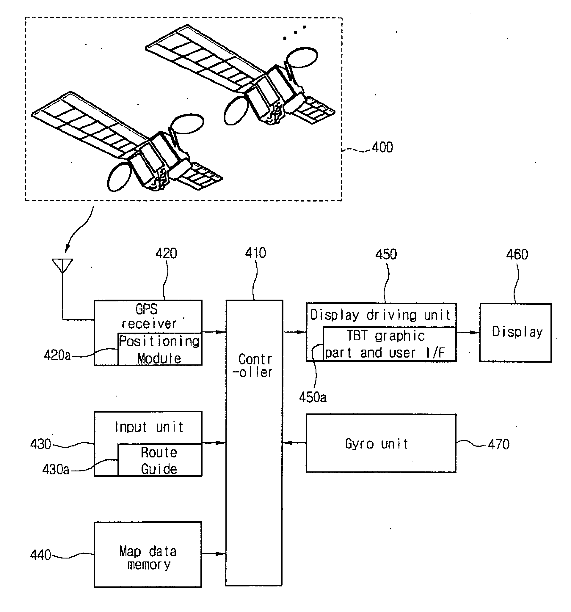
[0065]FIG. 4 is a block diagram illustrating components of the navigation system of the present invention, in which guidance for intersections and a progression rate of a car in a complicated intersection is provided.

[0066] Referring to FIG. 4, the navigation system according to the present invention includes a map data memory 440 for storing map data including a plurality of nodes and links and configuration points thereof that compose complicated intersections, an input unit 430, in which a user inputs information or designates a travelling path, the input unit 430 providing information on a route from an entrance road of a car to an exit road from an intersection connected to the entrance road, a GPS receiver 420 including a positioning module 420a that detects a present position...


PUM


Abstract

The present invention relates in general to a navigation system, more particularly, to a navigation system and an operating method thereof, in which the navigation system shows the configuration of a complicated intersection a driver is about to enter, and displays where to turn and a progression rate of the car on the path the driver is headed to. The navigation system includes a map data memory for storing map data; an input unit including a route guiding module, in which a user inputs information and / or designates a travelling path, and the input unit provides information on a route from an entrance road of a car to an exit road from an intersection; a GPS receiver including a positioning module for detecting a present position of the car on the basis of position information provided from at least one GPS satellite; a Gyro sensor for detecting a rotation angle of the car; a controller, which uses the map data from the map data memory, route information from the input unit, information from the GPS receiver about the present position of the car, and route information from the Gyro sensor, to generate the configuration of an intersection the user is supposed to enter and an arrow indicating a driving route to the user, and to display a progression rate of the car along the route; and a display driving unit for displaying the configuration of the intersection and the arrow for route guidance, on the basis of output data from the controller, and for performing a graphic operation on the configuration, thereby a gradual progression rate of the car is indicated in the directional arrow.

Description

BACKGROUND OF THE INVENTION [0001] 1. Field of the Invention [0002] The present invention relates in general to a navigation system, more particularly, to a navigation system and an operating method thereof, in which the navigation system shows the configuration of a complicated intersection a driver is about to enter, and displays where to turn and a progression rate of the car on the path the driver is headed to. [0003] 2. Discussion of the Background Art [0004] In general, a navigation system marks on a map displayed on a screen a present position of a moving object that is calculated on the basis of information received from a Global Positioning System satellite (hereinafter, it is referred to as ‘GPS’). [0005] Also, the navigation system provides a driver with any kind of information the driver needs for travelling, such as, travelling direction of the moving object, distance to a destination, present driving speed of the moving object a path to the destination set by the drive...

Claims


Application Information

Patent Timeline
IPC IPC(8): G01C21/00G01C21/36G01S1/00G09B29/00G08G1/0969G09B29/10
CPCG01C21/3632G08G1/0969
Inventor KIM, HEE JEONG
Owner LG ELECTRONICS INC
Learn More