Engine start control apparatus and method

a technology for starting and controlling apparatus, applied in the direction of electric control, engine starters, speed sensing governors, etc., can solve the problem of reducing fuel economy

Active Publication Date: 2008-01-31
NISSAN MOTOR CO LTD
View PDF7 Cites 35 Cited by
  • Summary
  • Abstract
  • Description
  • Claims
  • Application Information

AI Technical Summary

Benefits of technology

[0009] In accordance with embodiments of the present invention, an engine start control method includes retarding an ignition timing when an engine rotation speed at start of the engine reaches a target idling rotation speed, opening an intake throttle before the retarding of the ignition timing by a response delay period from when an intake throttle opens until air reaches a combustion chamber of the engine, and increasing an amount of fuel injected into a cylinder expected to be in a combustion stroke when the start engine rotation speed reaches the target idling rotation speed, and in the exhaust stroke immediately before the start engine rotation speed reaches the target idling rotation speed.
[0010] In accordance with embodiments of the present invention, even in the cold start situation, after the complete ignition, the engine rotation speed swiftly settles down to the target rotation speed at the time of idling.

Problems solved by technology

In a cold start of the engine, meaning that the engine and other components are not still warm from previous use, a catalyst is in an inactive state since its temperature is low and is incapable of purifying an exhaust gas.
This reduces the fuel economy because more fuel is consumed at the higher engine rotation speed.

Method used


Image

  • Engine start control apparatus and method
  • Engine start control apparatus and method
  • Engine start control apparatus and method

Examples


first embodiment

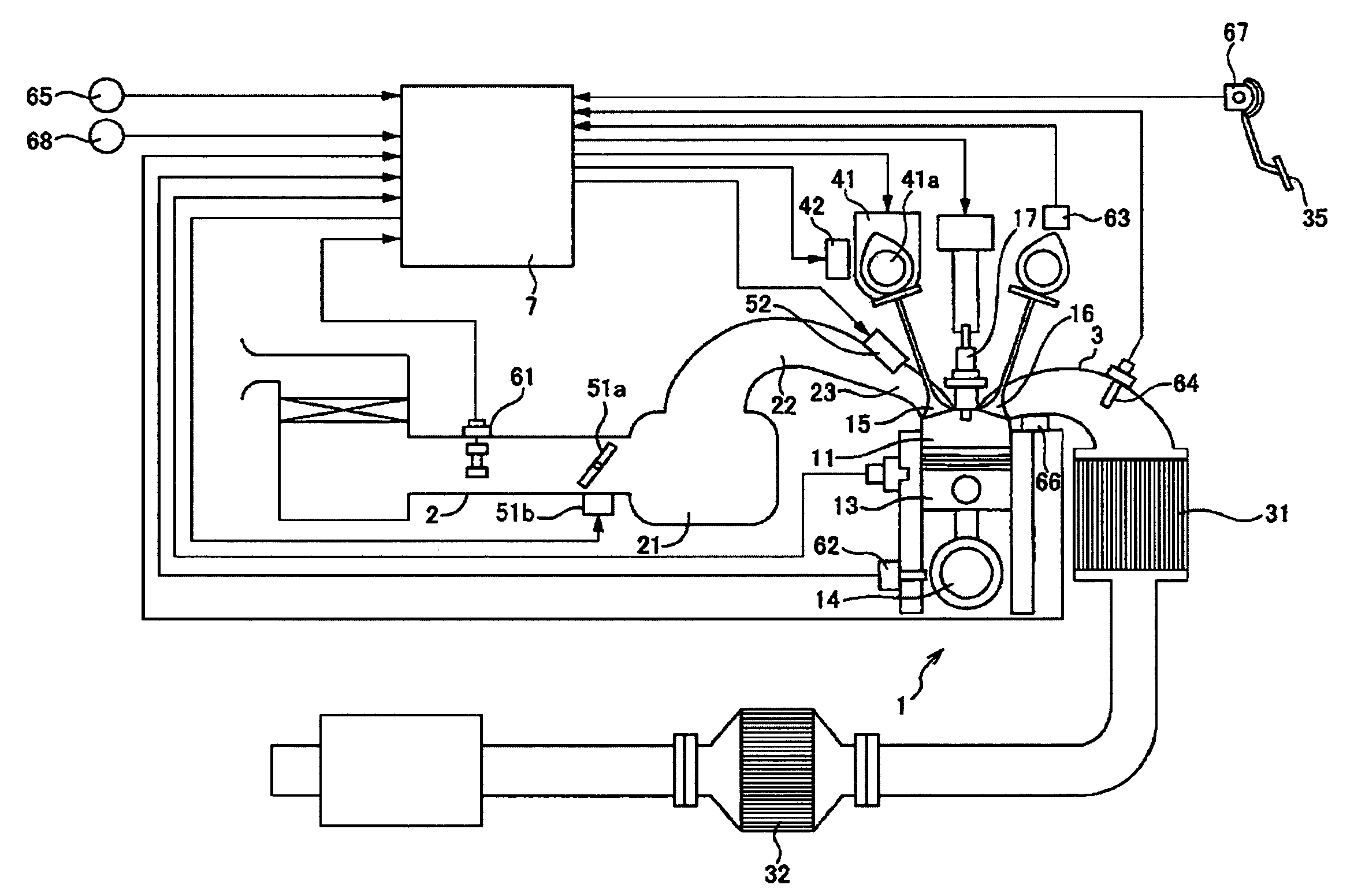
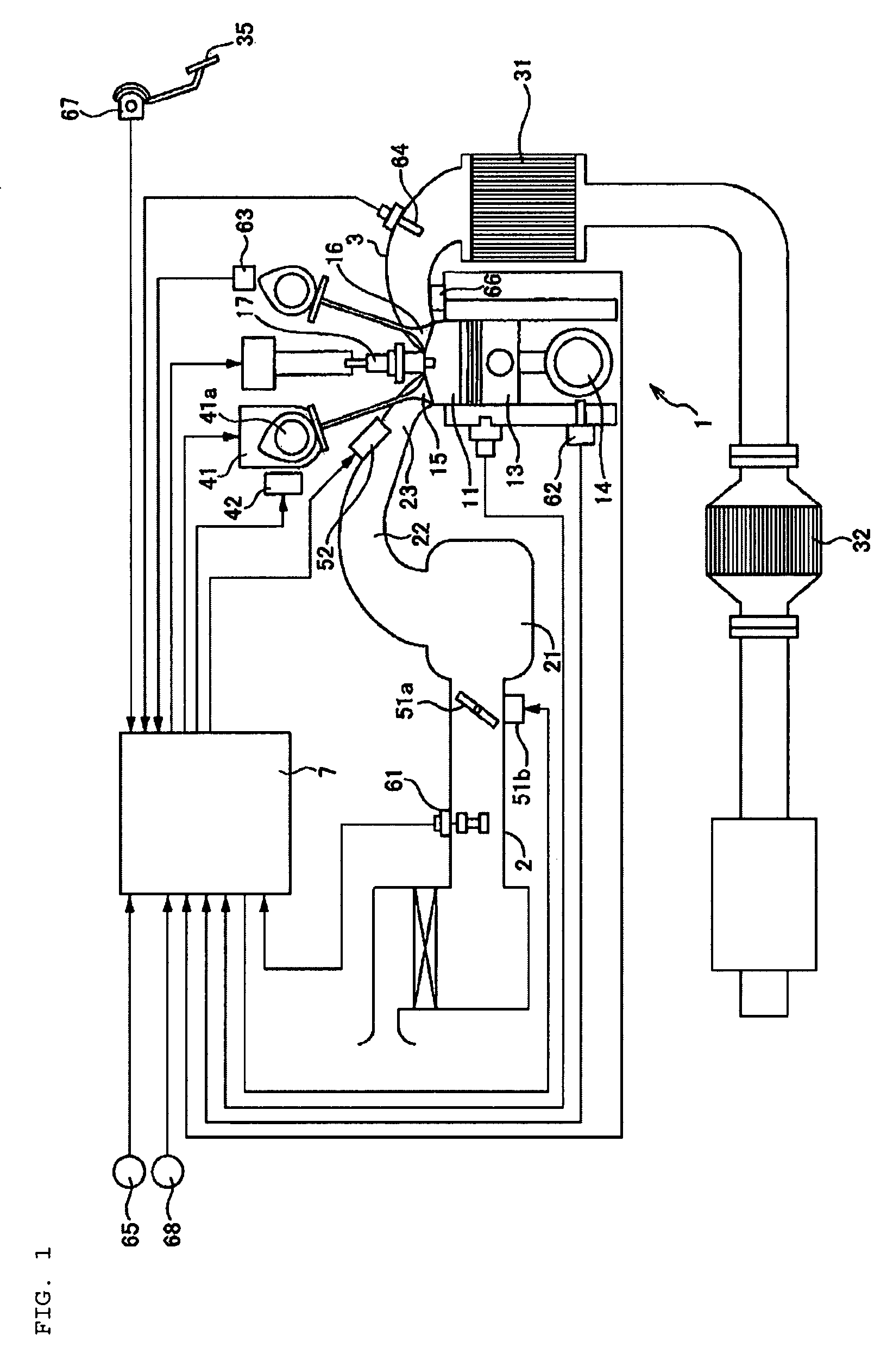
[0038]FIG. 1 is a diagram schematically showing an arrangement of an engine start control apparatus according to the present invention.

[0039] An intake throttle device 51 as intake control means and a fuel injection valve 52 as fuel supply means are installed in an intake air passage 2 of an engine 1, including an intake air collector 21. The intake throttle device 51 includes an intake throttle 51a and a throttle motor 51b. When a driver presses on an acceleration pedal 35, a controller 7 as control means determines a target torque in accordance with a signal from an accelerator position sensor 67, determines a target amount of air to attain the target torque, and controls a degree of opening of the intake throttle 51a with the aid of the throttle motor 51b so as to obtain the target air amount. When receiving a torque request signal for constant speed traveling by an auto speed control device (ASCD) and a torque request signal for the rotation synchronization control to ease gear ...

second embodiment

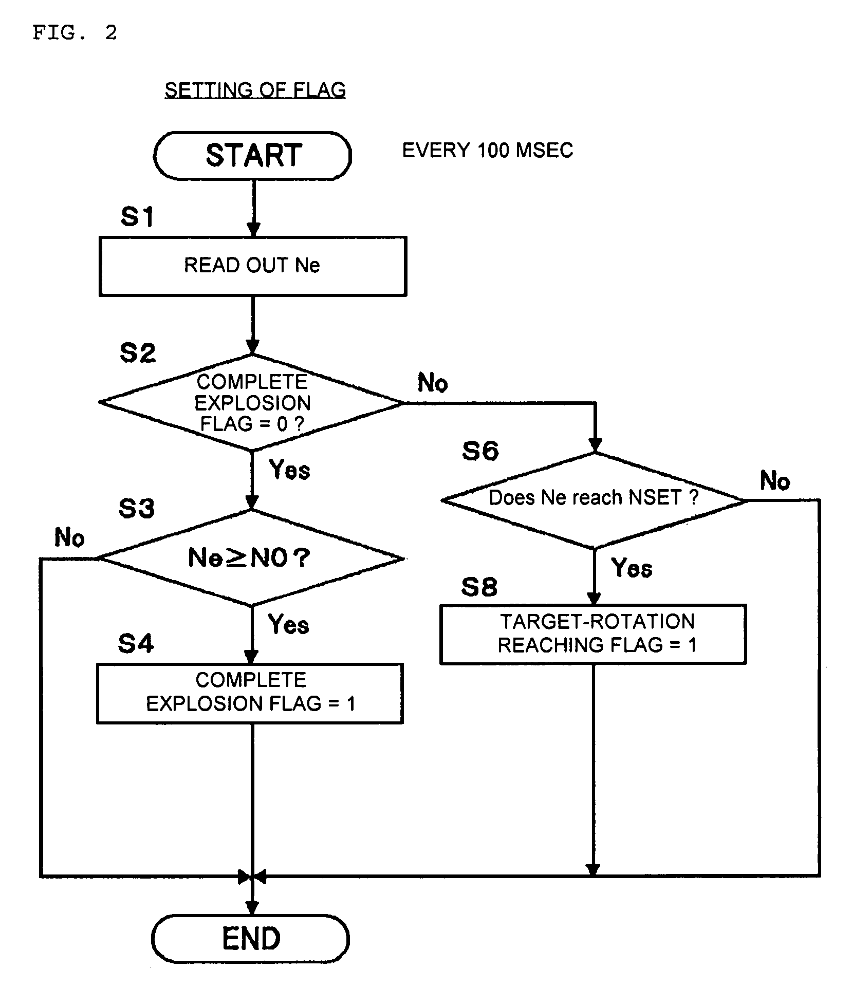
[0124] In the second embodiment, the controller determines a cylinder expected to be in the combustion stroke when the engine rotation speed at engine startup reaches the target idling rotation speed NSET. The controller increases the amount of fuel injected into the cylinder and the cylinders preceding and subsequent to the former which are in the exhaust stroke immediately before the engine rotation speed reaches the target idling rotation speed NSET. In a specific control, a decision value NSET0 for determining a cylinder which is preceding by one in the ignition order is set for a cylinder expected to be in the combustion stroke when the engine rotation speed at engine startup reaches the target idling rotation speed NSET. When the expected engine rotation speed Nf reaches the decision value NSET0, the controller then increases the amount of fuel injected to three cylinders which will be in the exhaust stroke.

[0125] In this embodiment, the amount of fuel injected is successively...

third embodiment

[0126]FIG. 10 is a timing chart showing operations of an engine start control apparatus according to the present invention.

[0127] In the present embodiment, the following prediction is made on a cylinder estimated such that the expected engine rotation speed Nf reaches the target idling rotation speed NSET.

[0128] The controller predicts which cylinder, when counted from the current cylinder, is in the combustion stroke and has a rotation speed reaching the target idling rotation speed NSET on the basis of a finite difference of a quantity of change (inclination) of the expected engine rotation speed Nf (section C of FIG. 10). When the prediction is that the rotation speed of the cylinder will reach the target idling rotation speed, the controller increments the counter associated with the cylinder. The counter associated with the cylinder #1 is illustrated in section D of FIG. 10. Actually, the counters are provided in association with the respective cylinders. When a counter value...


PUM


Abstract

An engine start control apparatus includes an intake air amount control device for controlling an amount of air supplied to a combustion chamber, a fuel supply device for injecting fuel to be fed into the combustion chamber, and an igniting device for igniting the fuel. The engine start control apparatus further includes an engine operation state detecting unit for detecting an operation state of the engine, an ignition timing retard angle processing unit configured to retard an ignition timing from a start ignition timing to an ignition timing for catalyst warming-up acceleration in response to detection that the engine operation state has shifted to an idling operation state, an intake control device operation unit for operating an intake control device so as to supply such an amount of intake air as to keep the idling operation state when the engine operation state has shifted to the idling operation state, and an injection fuel amount increasing unit for increasing an amount of fuel injected into a cylinder to be shifted to a combustion stroke so as to be combusted in the combustion stroke when the engine operation state has shifted to the idling operation state.

Description

PRIORITY APPLICATION [0001] This application claims priority from Japanese Patent Application Nos. 2006-233406, filed Aug. 30, 2006, and 2006-201784, filed Jul. 25, 2006, the contents of which are hereby incorporated by reference in their entireties. BACKGROUND OF INVENTION [0002] 1. Field of the Invention [0003] The present invention relates to an apparatus and method for controlling starting of an engine. [0004] 2. Description of the Related Art [0005] In a cold start of the engine, meaning that the engine and other components are not still warm from previous use, a catalyst is in an inactive state since its temperature is low and is incapable of purifying an exhaust gas. In this situation, it is important to activate the catalyst in order for the catalyst to begin to purify the exhaust gas. [0006] Japanese Patent Application Laid-Open (JP-A) No. 8-232645 discloses a technique for activating the catalyst after the engine is started. In the technique, in the cold start situation, a...

Claims


Application Information

Patent Timeline
Patent Type & Authority Applications(United States)
IPC IPC(8): F02N17/00F02N99/00
CPCF02D31/001F02D37/02F02D41/0002F02D41/06F02D41/08F02D41/1454Y02T10/42F02D2011/102F02P3/0414F02P5/1506F02P5/1508Y02T10/46F02D41/34Y02T10/40
Inventor I, SUNKIYASUDA, HAJIMENISHIZAWA, KIMIYOSHISATOU, KENICHIYOSHIOKA, DAISUKEMORI, KOUICHI
Owner NISSAN MOTOR CO LTD
Why Eureka
Try Eureka