Canter chipping heads having drive line slip joints

Inactive Publication Date: 2008-01-31
USNRKOCKUMS CANCAR
View PDF22 Cites 1 Cited by
  • Summary
  • Abstract
  • Description
  • Claims
  • Application Information

AI Technical Summary

Benefits of technology

[0007]As will be appreciated by those skilled in the art, the speed with which for example chipping heads in the prior art may be translated in and out relative to the feed path is limited in part by the overall weight of the machine that must be moved. Thus in the present invention the translation speed of the cut

Problems solved by technology

As will be appreciated by those skilled in the art, the speed with which for example chipping heads in the prior art may be

Method used


Image

  • Canter chipping heads having drive line slip joints
  • Canter chipping heads having drive line slip joints
  • Canter chipping heads having drive line slip joints

Examples


Example

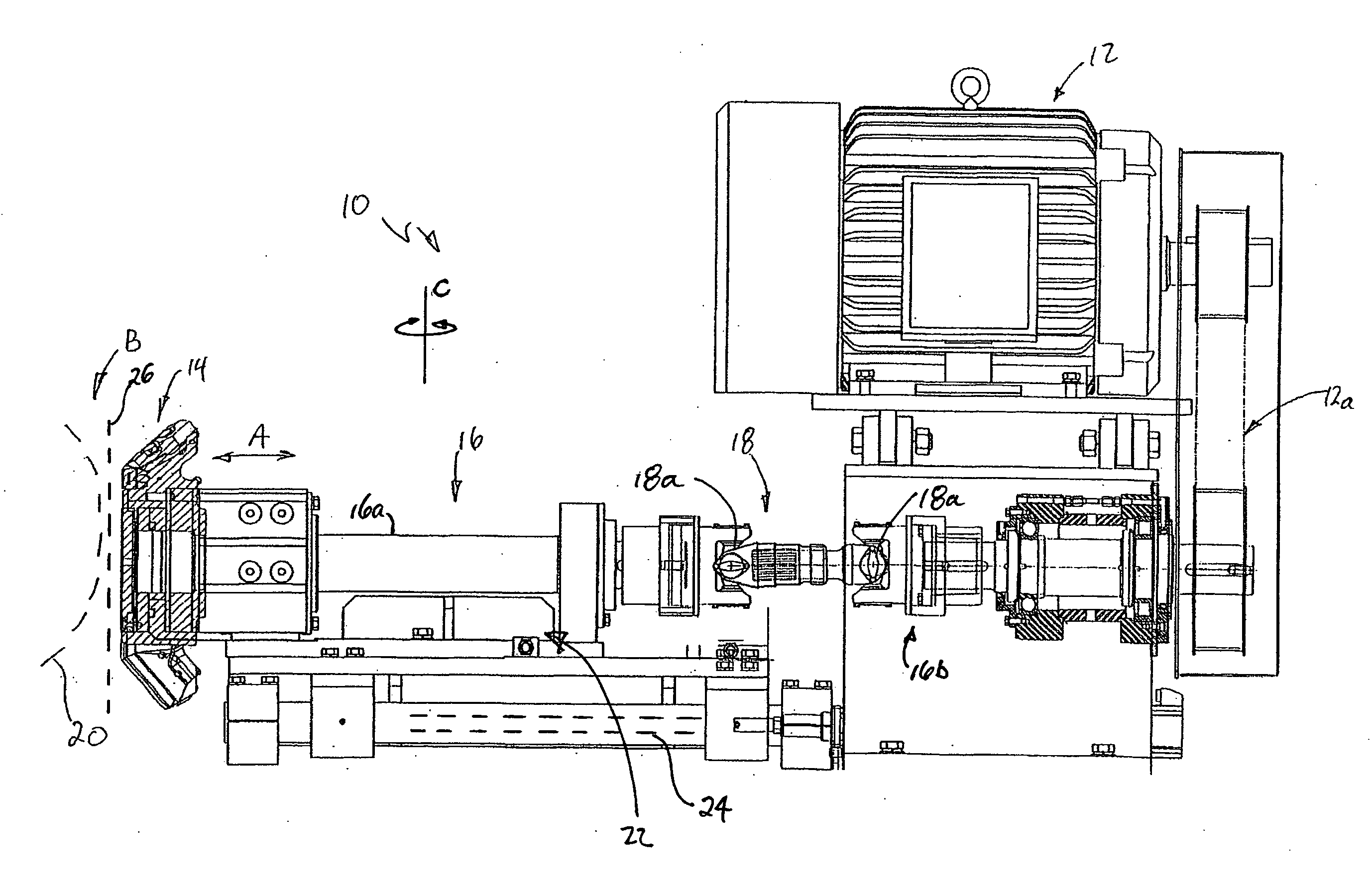
[0019]To increase productivity in a sawmill wood must be cut faster and with less gap between pieces. Speed has reached a limiting threshold as we are close to the maximum cutting abilities of saws and chip heads. Therefore the only remaining avenue left to increase throughput is to reduce gaps between pieces. Gaps are required to reset the cutting tools between pieces to some preferred positions as dictated by an optimizer. The ability to move the cutting tools quickly is dependent on the force available, the mass to be moved and the friction of the sliding members. Of these the most significant is the mass.

[0020]Canter or chipping heads are driven by an electric motor through a drive system of sheaves and belts to a rotating arbor, on the other end of which is the chipping head. This whole assembly is mounted on a structural base resting on slideways and moved by a linear positioner. This unit typically may weigh eight thousand to ten thousand pounds.

[0021]In order to reduce this ...


PUM


Abstract

A sawing or reducing assembly which includes at least one saw or reducing head such as a chipping head, at least one drive driving the saw or reducing head, and at least one drive line cooperating between the drive and the saw or reducing head, so as to rotatably drive the saw or reducing head. The saws or reducing heads, or at least some of them, are at least selectively transversely actuable so as to selectively translate transversely into a workpiece feed path as a workpiece is translated along the feed path into engagement with the workpiece. The drive is fixed in relation to the feed path. The drive line includes a corresponding slip joint allowing for relative movement between the drive and the saw or reducing head as the saw or reducing head is selectively translated transversely into the feed path.

Description

CROSS REFERENCE TO RELATED APPLICATION[0001]This application claims priority from U.S. Provisional Patent Application No. 60 / 833,275 filed Jul. 26, 2006 entitled Canter Chipping Heads Having Drive Line Slip Joints.FIELD OF THE INVENTION[0002]This invention relates to the field of active edgers or other sawing or reducing machines having saws or cutting heads translatable laterally into the feed-line of a workpiece, and in particular to a canter drive line driving chipping heads and having slip joints in the drive line so as to allow translation of the chipping heads independent of the drive.BACKGROUND OF THE INVENTION[0003]In the prior art applicant is aware of U.S. Pat. No. 5,816,302 issued Oct. 6, 1998 to Newnes, wherein the use of chipping heads is discussed for curve sawing. FIGS. 1-4 from that patent are included as illustrating the use of conical chipping heads, although the present invention is not intended to be limited to only the use in conjunction with conical chipping he...

Claims


Application Information

Patent Timeline
IPC IPC(8): B27B1/00
CPCB27L11/007B27B7/00
Inventor STROUD, BRIAN
Owner USNRKOCKUMS CANCAR
Why Eureka
Try Eureka