
Fan shroud for automotive applications

a technology for automotive applications and fan shrouds, which is applied in vehicle components, vehicle heating/cooling devices, transportation and packaging, etc., can solve the problems of ram airflow, high vehicle speed airflow performance, and limited electrical power available to the fan system, so as to achieve adequate idle airflow, maximum airflow, and high operating speed

Inactive Publication Date: 2008-01-31
VALEO INC
View PDF27 Cites 19 Cited by
  • Summary
  • Abstract
  • Description
  • Claims
  • Application Information

AI Technical Summary

Benefits of technology

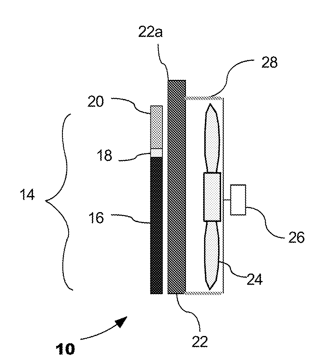
[0019]In various aspects of the present invention, a fan shroud (when used in automotive cooling applications hereinto referred to as a “cooling fan shroud”) is designed that provides or allows for higher airflow to be achieved through the radiator and oil cooler heat exchangers for higher vehicle operating speeds; this higher airflow is higher than those currently achieved using current art fan shrouds. Any measurable improvement in airflow is of benefit. The amount of increased airflow of the partial coverage shroud design is driven by combinations of independent variables such as: specific areas of covered and non-covered heat exchanger surface area, meter per second value of vehicle ram flow, fan power level, vehicle speeds, heat exchanger pressure restriction levels, etc. The cooling fan shroud designs, in accordance with aspects of the present invention, when used in conjunction with condenser related applications, actually increases condenser airflow for idle operation, without adding cost to the overall system.
[0021]One embodiment of the present invention, in various aspects, can be used with a variety of cooler modules. In some of the embodiments of these aspects, a combo-cooler design (design wherein tubes share a common set of manifolds) (see, for example, US Patent Application No. US2003-0209344A1, published on Nov. 13, 2003, incorporated herein by reference and made a part hereof), is used for the heat exchanger. In heat exchanger assemblies comprising a fan cooling module, a combo-cooler design heat exchanger is used in combination with a partial coverage shroud design. By partial coverage shroud design, one meaning is that the shroud covers less than 100% of the frontal area established by the perimeter of the airflow area of the heat exchangers. A heat exchanger assembly comprising a fan cooling module and heat exchanger, and, particularly, a combo-cooler design heat exchanger, combines the benefits and cost savings of a combo-cooler design along with a partial coverage shroud design. In combo-cooler design heat exchangers comprising an oil cooler portion and a condenser portion, the partial coverage shroud allows ram airflow full and / or virtually unimpeded access to areas of the oil cooler portion of the combo-cooler, as well as a radiator, where present, to higher levels of ram airflow at higher vehicle speeds while maintaining 100% coverage of the condenser portion of the combo-cooler heat exchanger face area.
[0023]This configuration allows cooling flow to be maximized through the radiator and oil cooler portions of the combo-cooler for grade trailer tow requirements, while maintaining or improving airflow though the condenser for Idle operating conditions.
[0024]This maximizes airflow at higher speed trailer grade operating conditions while actually increasing idle airflow through the condenser portion.
[0025]Aspects of the present invention, therefore, have the advantage of the combo-cooler design along with the advantage of a unique fan shroud configuration. The overall combination of combo-cooler heat exchanger and cooling fan shroud design is particularly useful in light truck and SUV market segments where high speed trailer tow requirements are often a worst case cooling system design consideration. These aspects provide both a cost and a performance advantage formerly not seen in other heat exchanger assemblies. The cooling fan shroud, though providing a competitive advantage in and of itself in automotive applications, its use in combination with a specific heat exchanger design, provides heretofore unforeseen advantages when used with various combo-cooler heat exchanger designs.
[0026]Illustrated aspects of the present invention provide for a combo-cooler design or type heat exchanger having a cooling fan shroud, wherein the shroud substantially covers the condenser. For example, under various conditions, it might be best for idle operation to cover 100% of the condenser, but there could be times where covering less than 100% of the condenser is desired by specification to improve high speed cooling, even at some expense to maximizing idle condenser performance. About 100%, of the condenser tube face area of the condenser core portion of the combo-cooler design heat exchanger for example, can be covered, leaving portions of the oil cooler tube area of the combo-cooler design heat exchanger open to or subjected to ram flow.

Problems solved by technology

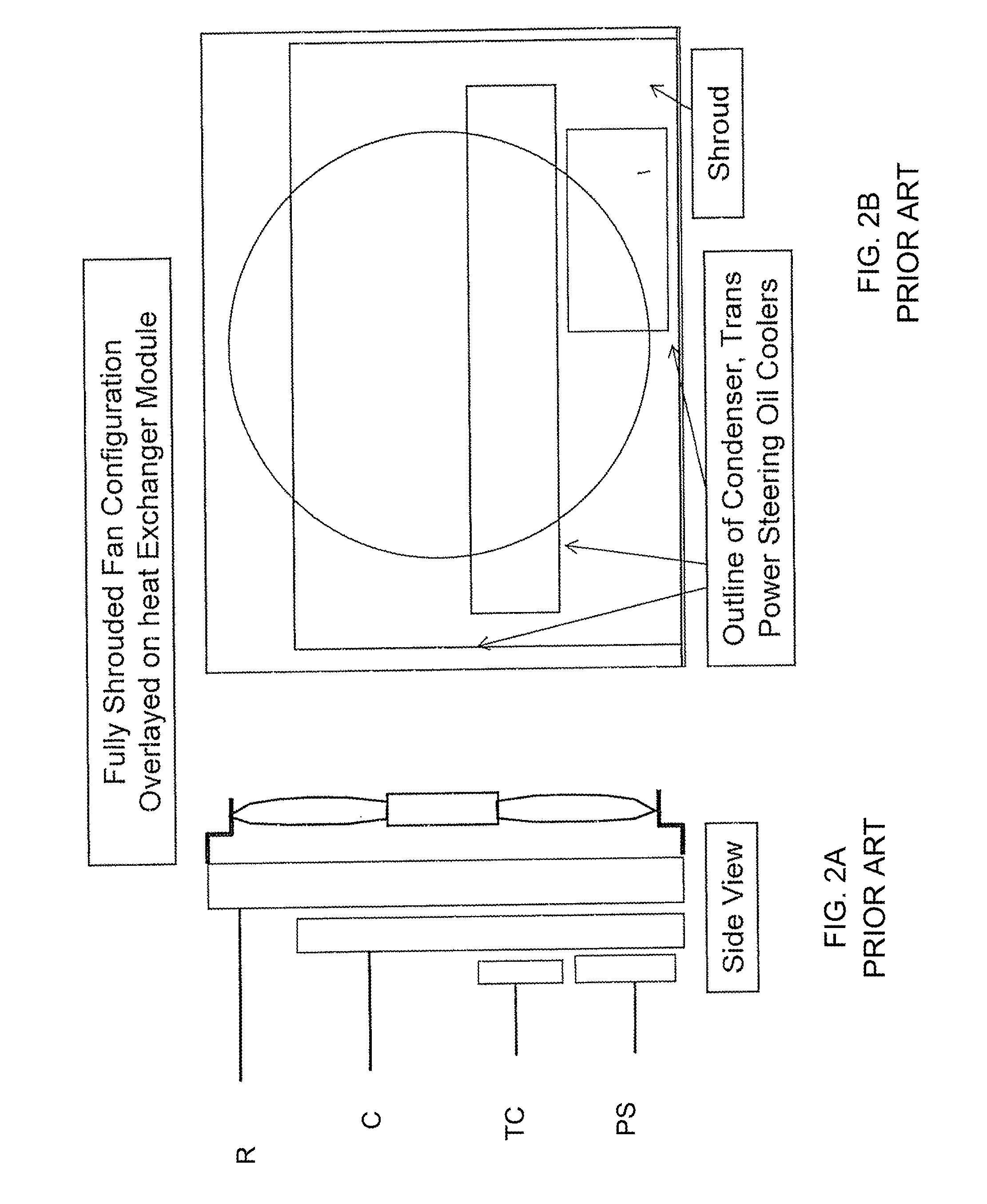
Fan systems with 100% coverage of cooling module flow area often have issues with airflow performance at higher vehicle speeds.
Electrical power available for the fan system is often limited.
Ram airflow at vehicle speeds as low as 45 MPH often overpowers the capability for the electric fan system to draw cooling airflow through the heat exchanger module.
All these solutions present problems in one way or another.
This increases flow for higher vehicle speed conditions, but reduces flow through the condenser at idle conditions negatively impacting condensing and A / C system performance at idle conditions.
Any additional loss in condensing performance is not desired.
This offset reduces shroud effectiveness and results in lower idle airflow than what would occur for a fan centered in the radiator core face area.
In addition, the airflow at higher vehicle speeds with the flap configuration is not as much as would be achieved for a partial coverage shroud configuration with open area matching the flap area.
In addition, flaps add an extra part and associated part number, add cost, and increase assembly labor.
These improve airflow at higher vehicle speeds, but cause an issue at idle.
Fan pulls air from the engine compartment through the open bypass hole which reduces total useful flow thru the heat exchanger.
One problem that still remains is how to maximize airflow for higher vehicle operating speeds while maintaining adequate idle airflow to satisfy condensing needs for the A / C system.

Method used


Image

  • Fan shroud for automotive applications
  • Fan shroud for automotive applications
  • Fan shroud for automotive applications

Examples


Embodiment Construction

[0047]In general, various aspects of the present invention provide for a number of advantages. For example, flow through transmission oil cooler is increased during trailer tow grade test point where transmission cooling requirements are at their highest. Trailer tow grade testing usually occurs with vehicle speeds of 55 to 65 MPH. These speeds are typically high enough for ram flow to overcome the flow potential of an electric fan system. Aspects of the present invention allow for improved cooling performance which may allow a reduction of size and cost of the oil cooler portion of the combo cooler.

[0048]Total radiator airflow, as described hereinabove, is increased for trailer grade test conditions in aspects of the present invention with cooling fan shroud configurations (for example, a 100% coverage shroud configuration), which is different from a flap, or a ram flow bypass hole design. Aspects of the present invention, therefore, may not only allow reduction of size and cost of...


PUM


Abstract

A heat exchange system and method for use with a combo-cooler heat exchanger as shown. In one embodiment, a combination of a heat exchanger module with a combo-cooler heat exchanger and a fan shroud is disclosed wherein the fan shroud covers approximately one-hundred percent of the condenser of the combo-cooler heat exchanger and leaves portions of the fluid coolers of the combo-cooler open to ram airflow.

Description

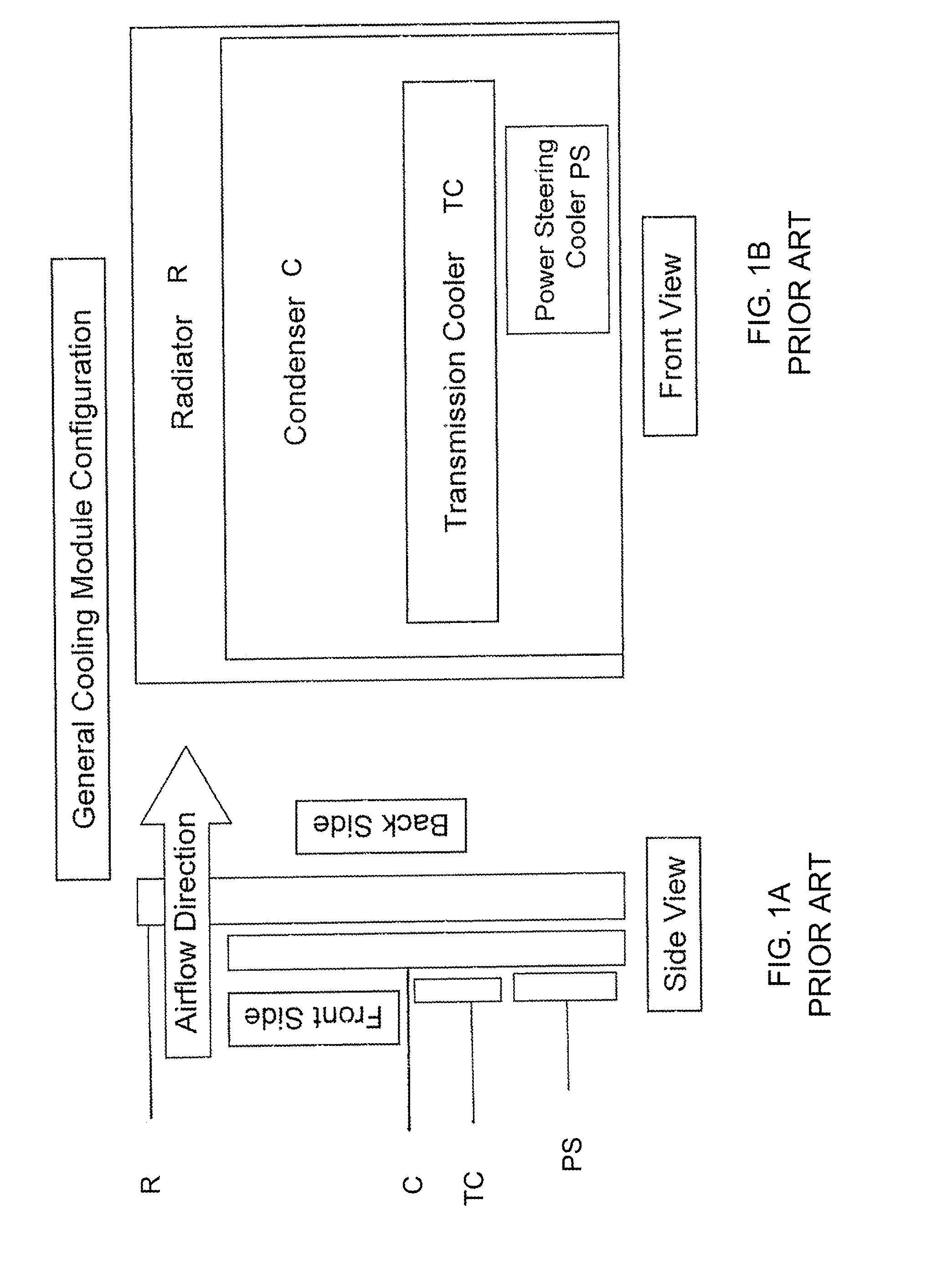
CROSS-REFERENCE TO RELATED APPLICATION[0001]This application claims the benefit of U.S. provisional application Ser. No. 60 / 834,380, filed Jul. 31, 2006, which is incorporated herein by reference and made a part hereof.BACKGROUND OF THE INVENTION[0002]1. Field of the Invention[0003]This invention relates to fan shrouds designed to hold cooling fans in automotive applications, such as automotive front end heat exchanger modules, are described.[0004]2. Description of the Related Art[0005]Front end heat exchanger cooling modules typically have a radiator (e.g. providing cooling utilizing engine coolant), a condenser (e.g., providing cooling for cabin HVAC systems), and often have auxiliary air to oil coolers used to provide cooling for transmission and power steering fluid or for engine oil. These auxiliary air to oil coolers are typically installed in front of the condenser. The fan content is usually installed on the downstream side of the radiator core face. Typical configurations f...

Claims


Application Information

Patent Timeline
IPC IPC(8): B60H1/32
CPCB60H1/00328
Inventor SAVAGE, JOHN R.
Owner VALEO INC
Learn More