Heat exchanger assembly

a heat exchanger and assembly technology, applied in the direction of indirect heat exchangers, stationary conduit assemblies, lighting and heating apparatus, etc., can solve the problems of uneven distribution of refrigerant, decrease and unfavorable heat exchange performance, so as to improve the heat exchange performance of the heat exchanger assembly and prevent separation. , the effect of cost-effective, flexible and efficien

Inactive Publication Date: 2008-01-31
DELPHI TECH INC
View PDF37 Cites 106 Cited by
  • Summary
  • Abstract
  • Description
  • Claims
  • Application Information

AI Technical Summary

Benefits of technology

[0015]Accordingly, the present invention provides a heat exchanger assembly including an insert that provides a cost effective, flexible, and efficient solution for uniformly distributing and directing a heat exchange fluid to a plurality of flow tubes within the heat exchanger assembly. Uniform distribution of the heat exchange fluid prevents separation and distribution problems encountered in previous heat exchanger assemblies while increasing heat exchange performance of the heat exchanger assembly. The insert may include various configurations of the orifices. For example, the orifices may be different in size, shape and spacing. The insert may be made into any length for spanning a length or a portion of the length of the first single-piece manifold. The insert may easily be slid into, within, and from the first single-piece manifold for forming a plurality of configurations and passes within the heat exchanger assembly. The orifices and the distribution chamber efficiently and uniformly distribute the heat exchange fluid to each one of the flow tubes for increasing heat exchange performance of the heat exchanger assembly.

Problems solved by technology

However, due to poor internal distribution of the refrigerant, and temperature and pressure differences within the manifolds and the flow tubes, some of the flow tubes receive more or less of the refrigerant than the other flow tubes, causing an unequal heat transfer burden on each one of the flow tubes, which decreases heat exchange performance of the heat exchanger assembly.
However, there is still uneven distribution of the refrigerant between each of the individual flow tubes within each of the passes.
This increased size magnifies the aforementioned distribution problems of the refrigerant within the heat exchanger assembly, and further adds to manufacturing costs due to the increased difficulty of properly locating and fixing the baffles within each of the manifolds to form the passes.
Velocity and distribution of the refrigerant within the heat exchanger assembly varies between the cooling and heating modes and can further decrease heat exchange performance of the heat exchanger.
Separation of the phases adds to the already present distribution problem within the passes, which further decreases overall heat exchange performance of the evaporator.
Separation of the two-phase refrigerant can also cause localized icing or frosting of individual or groups of flow tubes within the evaporator, causing plugging of the flow tubes and yet further lowering the heat exchange performance of the evaporator.
However, the distributor tube in the '083 patent is welded in place, and therefore is not movable or removable from the manifold.
Due to the distributor tube requiring welding to remain in place within the manifold, manufacture of the refrigerating coil is difficult due to demands of properly locating and welding the distributor tube in place within the manifold.
In addition, the distributor tube is limited to a one-pass configuration, due to the distributor tube extending the length of the manifold.
However, both the shell and tube evaporator and the plate type heat exchanger are limited to the same '083 patent one-pass configuration limitation.
However, extruded manifolds are typically expensive when compared to typical welded manifolds.
However, as in the '083 patent and the '303 patent, the internal walls are fixed and integral in the manifolds, thereby limiting the heat exchanger to one flow configuration.
In addition, the '407 patent suffers from distribution problems among each of the individual flow tubes within each of the passes.

Method used


Image

  • Heat exchanger assembly
  • Heat exchanger assembly
  • Heat exchanger assembly

Examples


Embodiment Construction

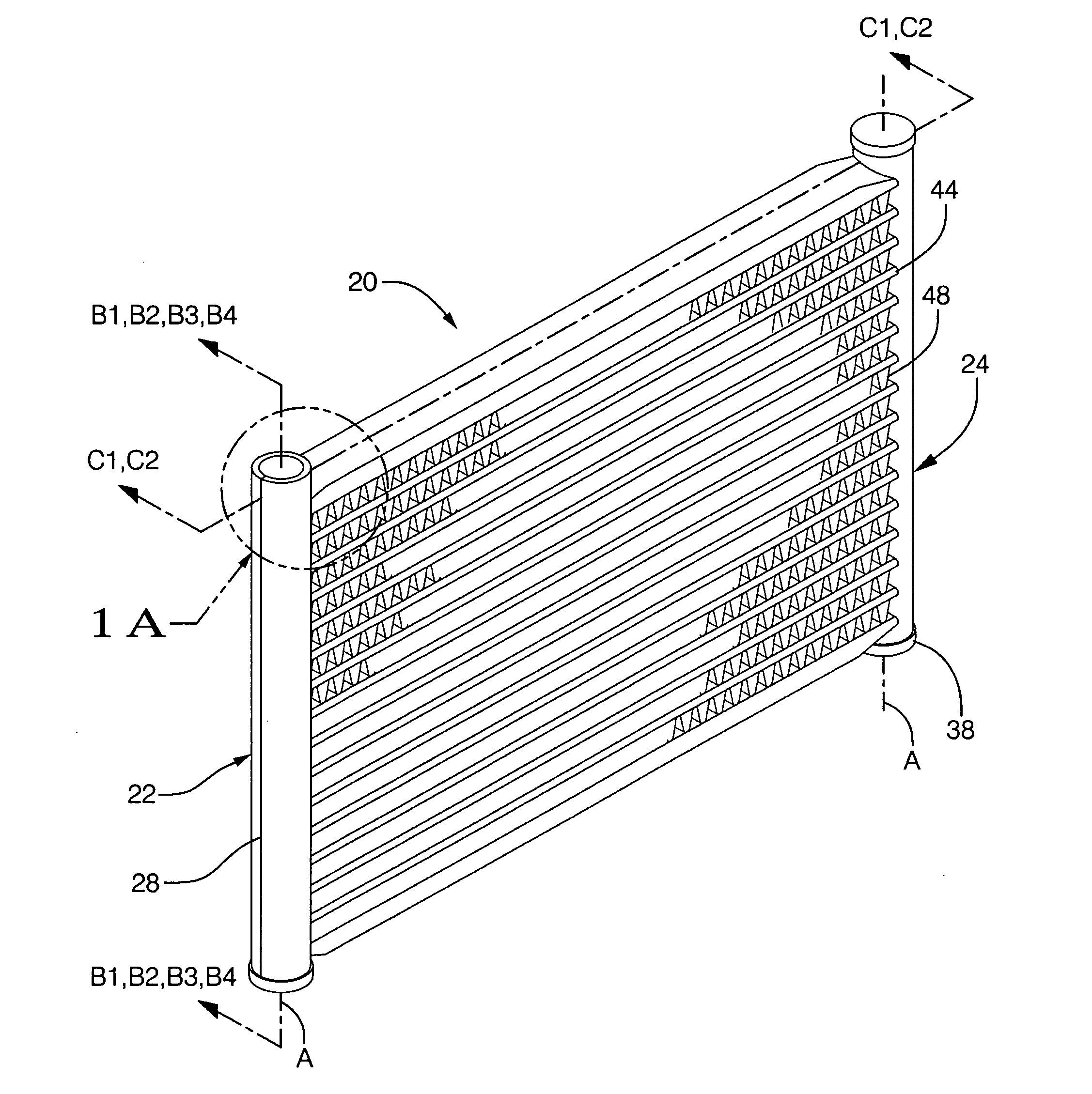
[0037]Referring to the Figures, wherein like numerals indicate corresponding parts throughout the several views, a heat exchanger assembly is shown generally at 20.

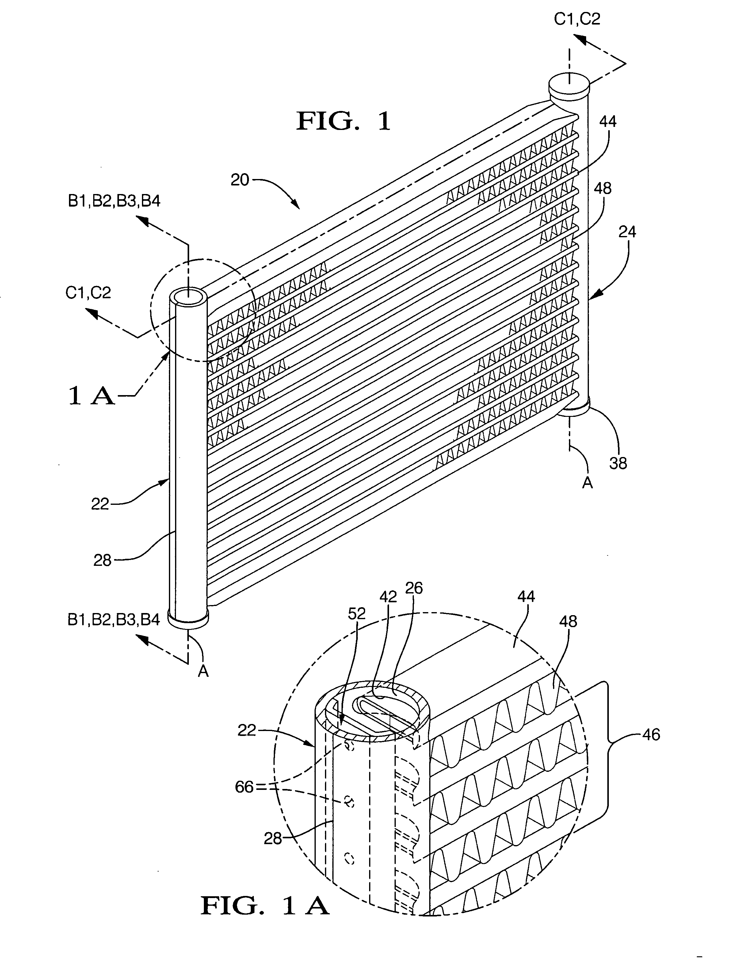
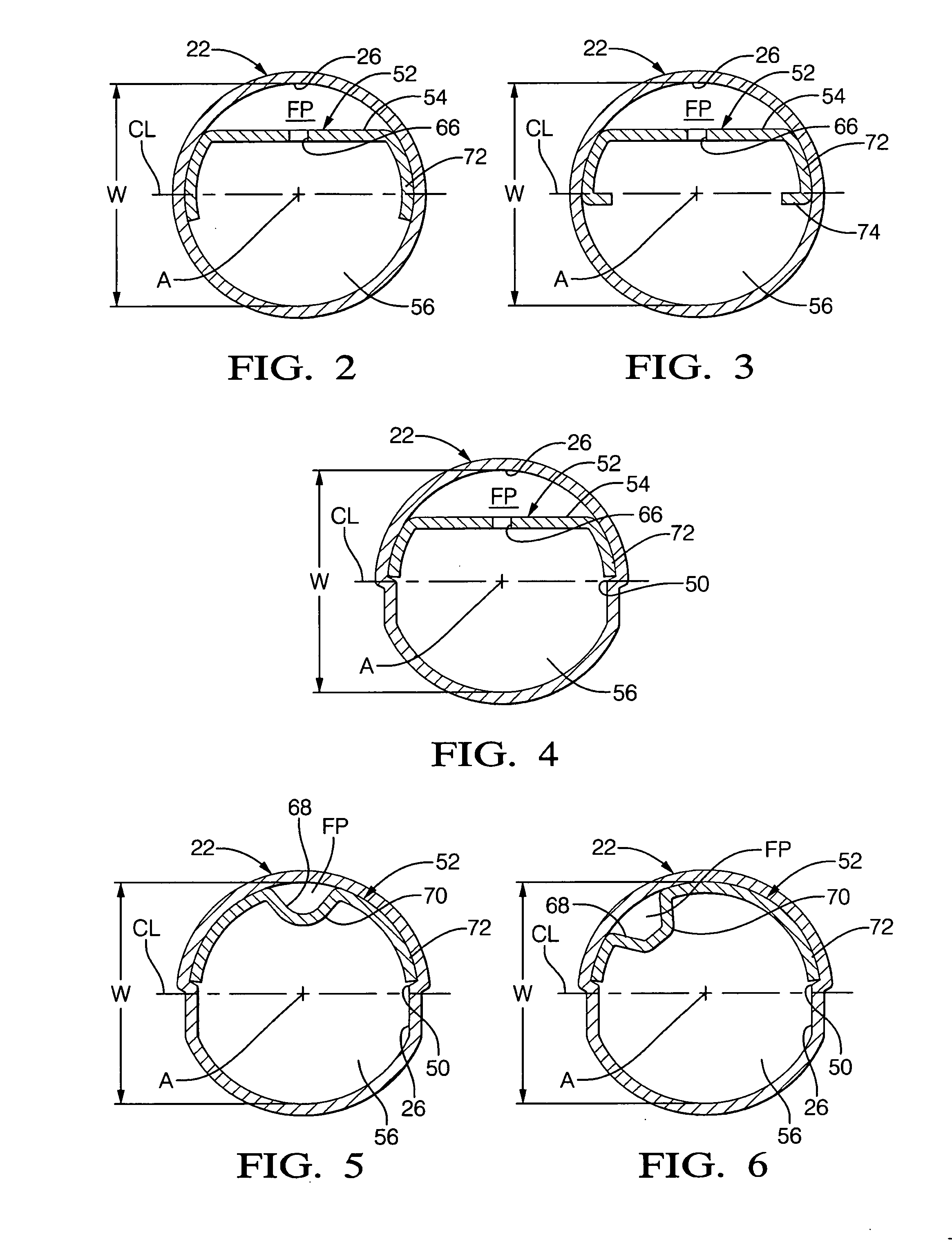
[0038]Referring to FIG. 1, a first embodiment of the heat exchanger assembly 20 is shown. The heat exchanger assembly 20 includes a first single-piece manifold 22 and a second single-piece manifold 24 spaced from and parallel to the first single-piece manifold 22. Referring to FIGS. 1A-6, each of the first and second single-piece manifolds 22, 24 (one shown) has a tubular wall 26 defining a flow path FP. In one embodiment, as best shown in FIGS. 2-6, the tubular wall 26 defines a circular shaped flow path FP. In other embodiments, the tubular wall 26 may define a triangular, an oval, a rectangular, a square, a polygon, or any other suitably shaped flow path FP as is known to those skilled in the art. The first and second single-piece manifolds 22, 24 may be used for receiving, holding, and distributing a heat exchange flu...


PUM


Abstract

A heat exchanger assembly includes a first single-piece manifold and a second single-piece manifold spaced from and parallel to the first single-piece manifold. Each of the first and second single-piece manifolds has a tubular wall defining a flow path. A plurality of flow tubes extend in parallel between the first and second single-piece manifolds and are in fluid communication with the flow paths. An insert having a distribution surface is slidably disposed in the flow path of the first single-piece manifold to establish a distribution chamber within the first single-piece manifold. A series of orifices defined in the distribution surface of the insert are in fluid communication with the flow path and the distribution chamber for uniformly distributing a heat exchange fluid between the flow path and the flow tubes.

Description

BACKGROUND OF THE INVENTION[0001]1. Field of the Invention[0002]The present invention generally relates to a heat exchanger assembly. More specifically, the present invention relates to a heat exchanger assembly including an insert for uniformly distributing and directing a heat exchange fluid within the heat exchanger assembly.[0003]2. Description of the Related Art[0004]Heat exchanger assemblies currently used in automobiles are being further developed and refined for use in commercial and residential heat pump systems due to their desirable high heat exchange performance. Typically, the heat exchanger assemblies used in automobiles include a pair of spaced and parallel manifolds with a series of parallel flow tubes extending therebetween. The flow tubes communicate a heat exchange fluid, i.e., a refrigerant, between the two manifolds. Air fins are disposed between the flow tubes to add surface area to the heat exchanger assembly for further aiding in heat transfer to or from ambi...

Claims


Application Information

Patent Timeline
Patent Type & Authority Applications(United States)
IPC IPC(8): F28F9/02
CPCF28D1/05375F28F9/0278F28F9/0246F28F9/0207
Inventor BEAMER, HENRY EARLRUNK, ROBERT MICHAEL
Owner DELPHI TECH INC
Why Eureka
Try Eureka