Permanent magnet electric motor

Inactive Publication Date: 2008-01-31
GM GLOBAL TECH OPERATIONS LLC
View PDF98 Cites 46 Cited by
  • Summary
  • Abstract
  • Description
  • Claims
  • Application Information

AI Technical Summary

Benefits of technology

[0010]The previously discussed and other drawbacks are overcome or alleviated by an electric motor for reducing torque ripple. The electric motor includes a rotor, a plurality of magnets positioned about the rotor, and a stator including a plurality of stator teeth configured to form at least two slot openings each having a slot

Problems solved by technology

Perhaps the most vexing issue with electric power assist steering systems has been torque ripple felt at the steering wheel.
Drivers accustomed to the smooth response of hydraulic power assist steering systems have reacted unfavorably to the torque ripple exhibited by electric power assist

Method used


Image

  • Permanent magnet electric motor
  • Permanent magnet electric motor
  • Permanent magnet electric motor

Examples


Example

[0028]The problem of torque ripple caused by the harmonics content in the line-to-line back-emf due to an imperfect sinusoidal back-emf waveform is identified and discussed in more detail in the commonly-assigned U.S. Pat. No. 6,380,658 issued on Apr. 30, 2002 and incorporated herein by reference in its entirety.

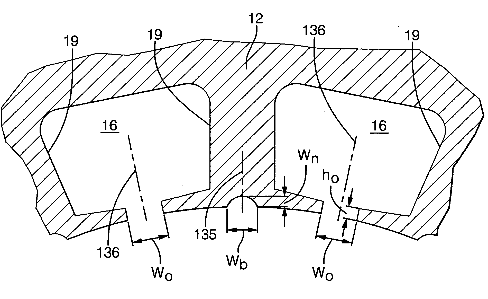
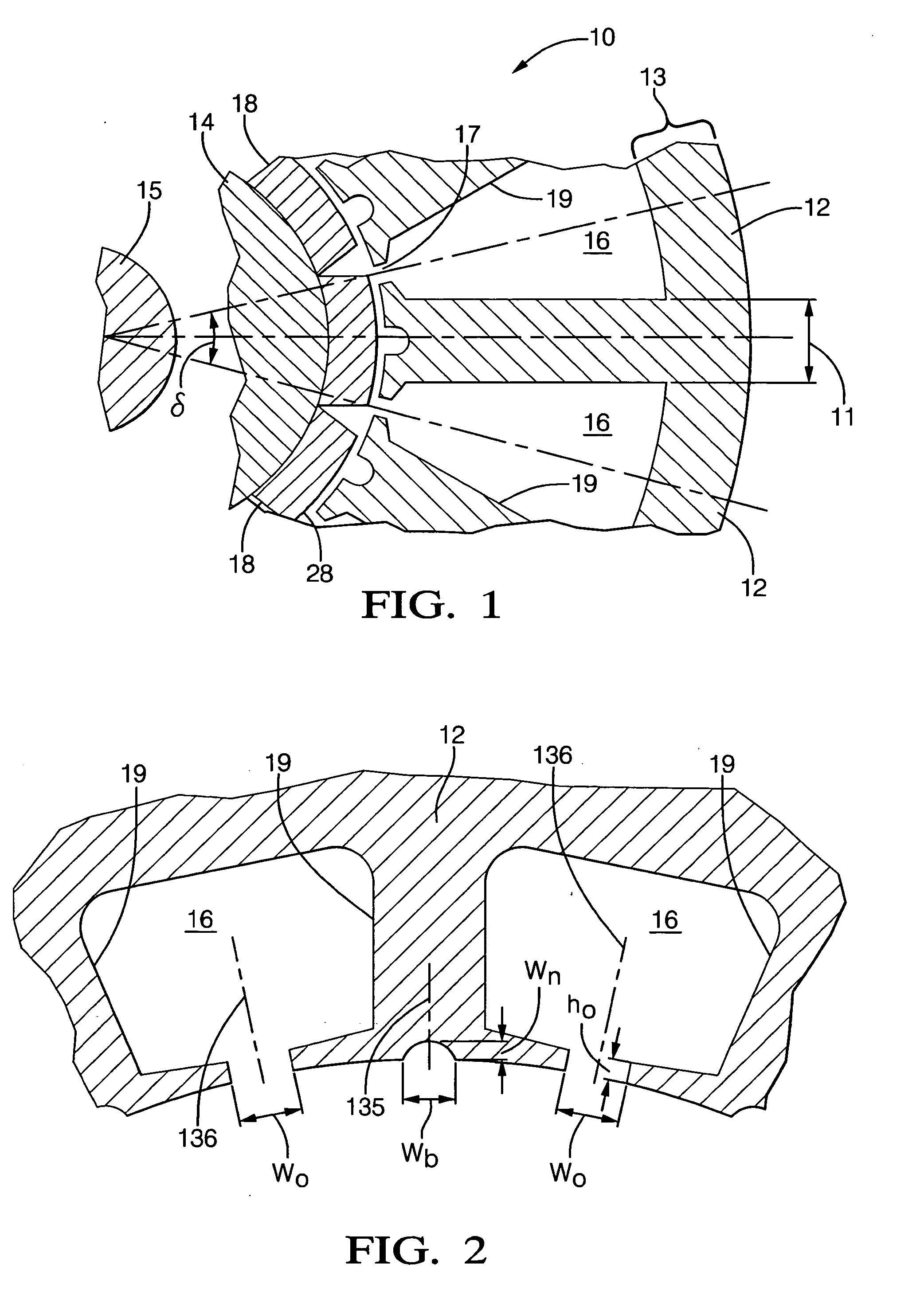
[0029]Pursuant to one embodiment of reducing or eliminating cogging torque, a brushless permanent magnet electric motor 10 having surface parallel magnets 18 is shown in FIG. 1. This embodiment provides a cost-effective, high-performance actuator for vehicular applications including electric power steering. Motor 10 includes a stator 12 having disposed therein a rotor 14 mounted to shaft 15. Stator 12 includes a plurality of teeth 19 arranged to form a plurality of slots 16. Windings are formed in the plurality of slots 16 for generating a magnetic field which interacts with the magnetic fields produced by surface parallel magnets 18. In one exemplary embodiment, stator 12 h...


PUM


Abstract

An electric motor for reducing torque ripple includes a rotor, a plurality of magnets positioned about the rotor, and a stator including a plurality of stator teeth configured to form at least two slot openings each having a slot opening width wo and a slot opening height ho. One or more of the stator teeth include a dummy channel having a channel height wn and a channel width wb. At least one of the slot opening width wo, the slot opening height ho, the channel height wn, and the channel width wb, are selected so as to minimize or reduce cogging torque.

Description

TECHNICAL FIELD[0001]This invention relates to torque ripple reduction in electric motors.BACKGROUND OF THE INVENTION[0002]Most motor vehicle steering systems produced today employ a power assist steering system to assist the driver in steering the front wheels. In general, power assist steering systems employ a hydraulic pump to provide pressurized fluid to a piston connected to or formed in the steering rack assembly, the pressure being regulated by a valve which is opened or closed by an amount that varies with the torque in the steering column. Thus, as the driver exerts more effort against the steering wheel, the valve is opened to provide more fluid to the piston, thereby assisting the driver in steering the vehicle.[0003]It has been heretofore known to provide a power assist steering system using an electric motor instead of pressurized hydraulic fluid as a source of motive force. This would improve fuel economy and reduce the manufacturing cost of the vehicle. Furthermore, s...

Claims


Application Information

Patent Timeline
IPC IPC(8): H02K21/12H02K23/42H02K1/00
CPCH02K5/22H02K29/08H02K29/03H02K11/0021H02K11/215
Inventor ISLAM, MOHAMMAD S.FISHER, PAUL M.SEBASTIAN, TOMYVENKITASUBRAMONY, RAMAKRISHNAN RAJAWONG, TOM C.
Owner GM GLOBAL TECH OPERATIONS LLC
Why Eureka
Try Eureka