Method and apparatus to correct an error in a switching power amplifier

Active Publication Date: 2008-01-31
SAMSUNG ELECTRONICS CO LTD
View PDF5 Cites 16 Cited by
  • Summary
  • Abstract
  • Description
  • Claims
  • Application Information

AI Technical Summary

Benefits of technology

[0013]The present general inventive concept also provides an error correction method of enhancing performance of a switching power amplifier through a digital feedback of an audio PWM signal according to an error remodulation method.

Problems solved by technology

However, the conventional class D power amplifier has a problem in that the nonlinearity of a power stage and ripple noise of a power supply unit deteriorate the audio performance of a system.
However, in the conventional switching power amplifier, an accurate analog loop filter should be separately designed in order to generate the error signal (Ve) in the error processing unit 110, and thus, complexity and cost of a system increase.
Also, in the conventional switching power amplifier, a correction operation should be performed in an analog domain, but it is very difficult to correct the characteristic of external noise or a nonlinear characteristic due to characteristics of an analog signal.

Method used


Image

  • Method and apparatus to correct an error in a switching power amplifier
  • Method and apparatus to correct an error in a switching power amplifier
  • Method and apparatus to correct an error in a switching power amplifier

Examples


Embodiment Construction

[0030]Reference will now be made in detail to the embodiments of the present general inventive concept, examples of which are illustrated in the accompanying drawings, wherein like reference numerals refer to the like elements throughout. The embodiments are described below in order to explain the present general inventive concept by referring to the figures.

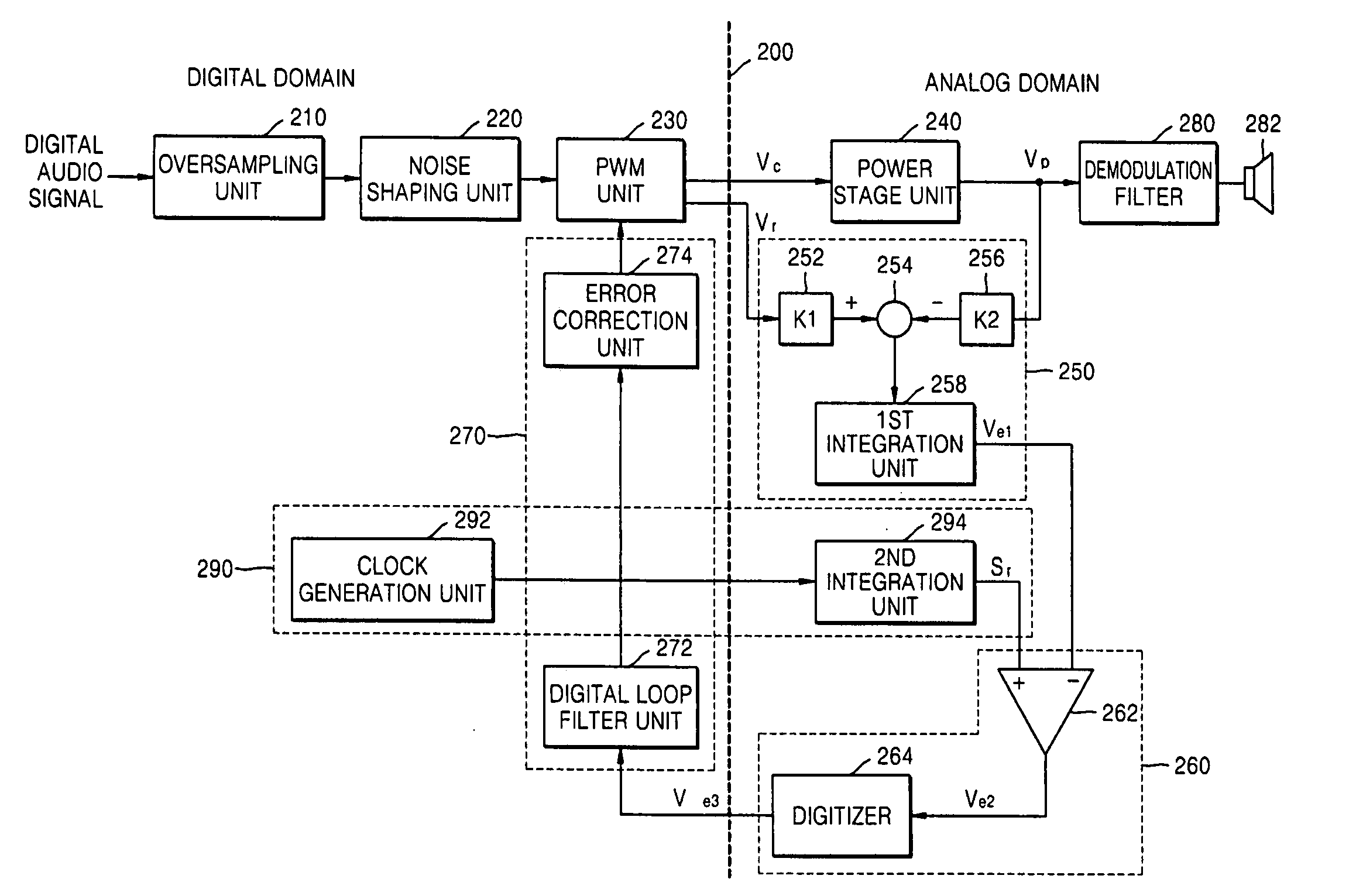
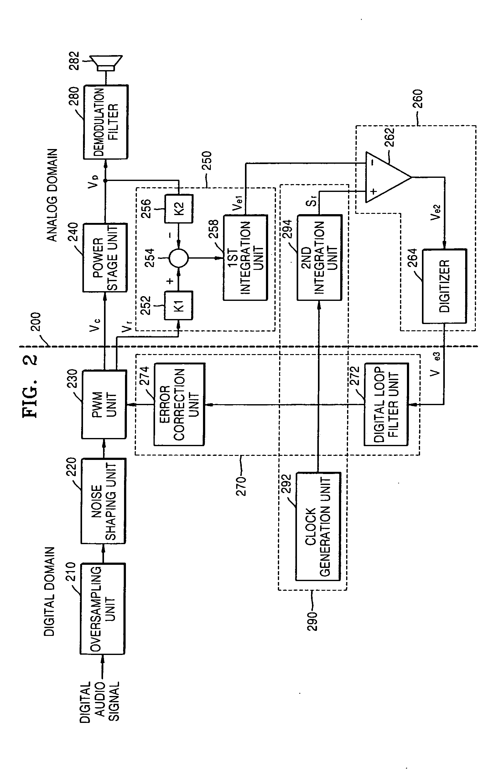
[0031]FIG. 2 is a block diagram illustrating an error correction apparatus of a switching power amplifier according to an embodiment of the present general inventive concept.

[0032]In the error correction apparatus of the switching power amplifier illustrated in FIG. 2, a dotted line 200 divides FIG. 2 into a left block and a right block. The left block is a portion of the error correction apparatus of the switching power amplifier that operates in a digital domain, while the right block is a portion of the error correction apparatus of the switching power amplifier that operates in an analog domain.

[0033]Referring to FIG. 2, the...


PUM


Abstract

An error correction method and apparatus to enhance performance of a switching power amplifier through digital feedback of an audio pulse width modulation (PWM) signal. The error correction apparatus includes a PWM unit to convert an audio signal into a PWM signal, a power stage unit to switch and amplify power of the PWM signal generated by the PWM unit, an error signal extraction unit to compare a reference PWM signal generated in the PWM unit with the PWM signal output from the power stage unit, thereby extracting an error signal, a remodulation unit to compare the error signal extracted in the error signal extraction unit with a reference signal having a predetermined slope, thereby modulating the error signal to an error PWM signal, and a signal correction unit to correct an error, by changing the pulse width of the PWM unit according to the error PWM signal generated in the remodulation unit.

Description

CROSS-REFERENCE TO RELATED APPLICATIONS[0001]This application claims priority under 35 U.S.C. 119 §(a) from of Korean Patent Application No. 10-2006-0071577, filed on Jul. 28, 2006, in the Korean Intellectual Property Office, the disclosure of which is incorporated herein in its entirety by reference.BACKGROUND OF THE INVENTION[0002]1. Field of the Invention[0003]The present general inventive concept relates to a switching power amplifier system, and more particularly, to an error correction method and apparatus to enhance the performance of a switching power amplifier by using a digital feedback technology of an audio pulse width modulation signal.[0004]2. Description of the Related Art[0005]A conventional switching power amplifier for audio signals may be classified as class A, class B, class AB and class D. The class D amplifier can reduce amplification efficiency drops occurring in class A, class B, and class AB amplifiers. The class D amplifier uses a method in which an audio s...

Claims


Application Information

Patent Timeline
IPC IPC(8): H03F3/38
CPCH03F3/217H03K7/08
Inventor PARK, HAE-KWANG
Owner SAMSUNG ELECTRONICS CO LTD
Why Eureka
Try Eureka