Starter having minimized electromagnetic switch

a technology of electromagnetic switch and starter, which is applied in the direction of engine starters, machines/engines, relays, etc., can solve the problems of difficult to minimize limit the radial direction of the electromagnetic switch, so as to minimize the dimension of the electromagnetic switch in the radial direction of the motor

Active Publication Date: 2008-01-31
DENSO CORP
View PDF12 Cites 14 Cited by
  • Summary
  • Abstract
  • Description
  • Claims
  • Application Information

AI Technical Summary

Benefits of technology

[0017]With the above configuration, the contacts cover has only the single terminal bolt for connecting the first fixed contact to the power source, without another one for connecting the second fixed contact to the motor as in the above-mentioned conventional starter. Further, since the terminal bolt extends through the end wall of the contac

Problems solved by technology

Accordingly, it is difficult to minimize the electromagnetic switch in the radial direction of the motor.
More specifically, it is necessary to secure a sufficient insulation distance between the two terminal bolts, and thus there is a limi

Method used


Image

  • Starter having minimized electromagnetic switch
  • Starter having minimized electromagnetic switch
  • Starter having minimized electromagnetic switch

Examples


first embodiment

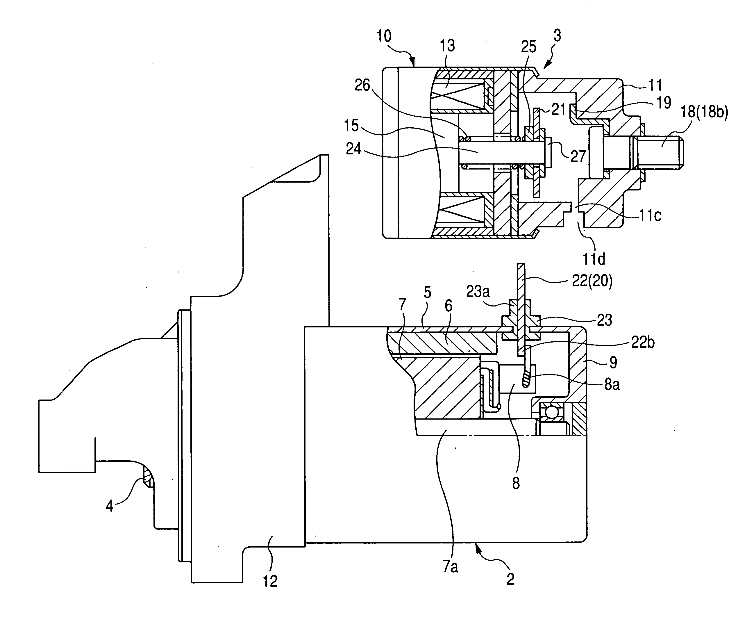
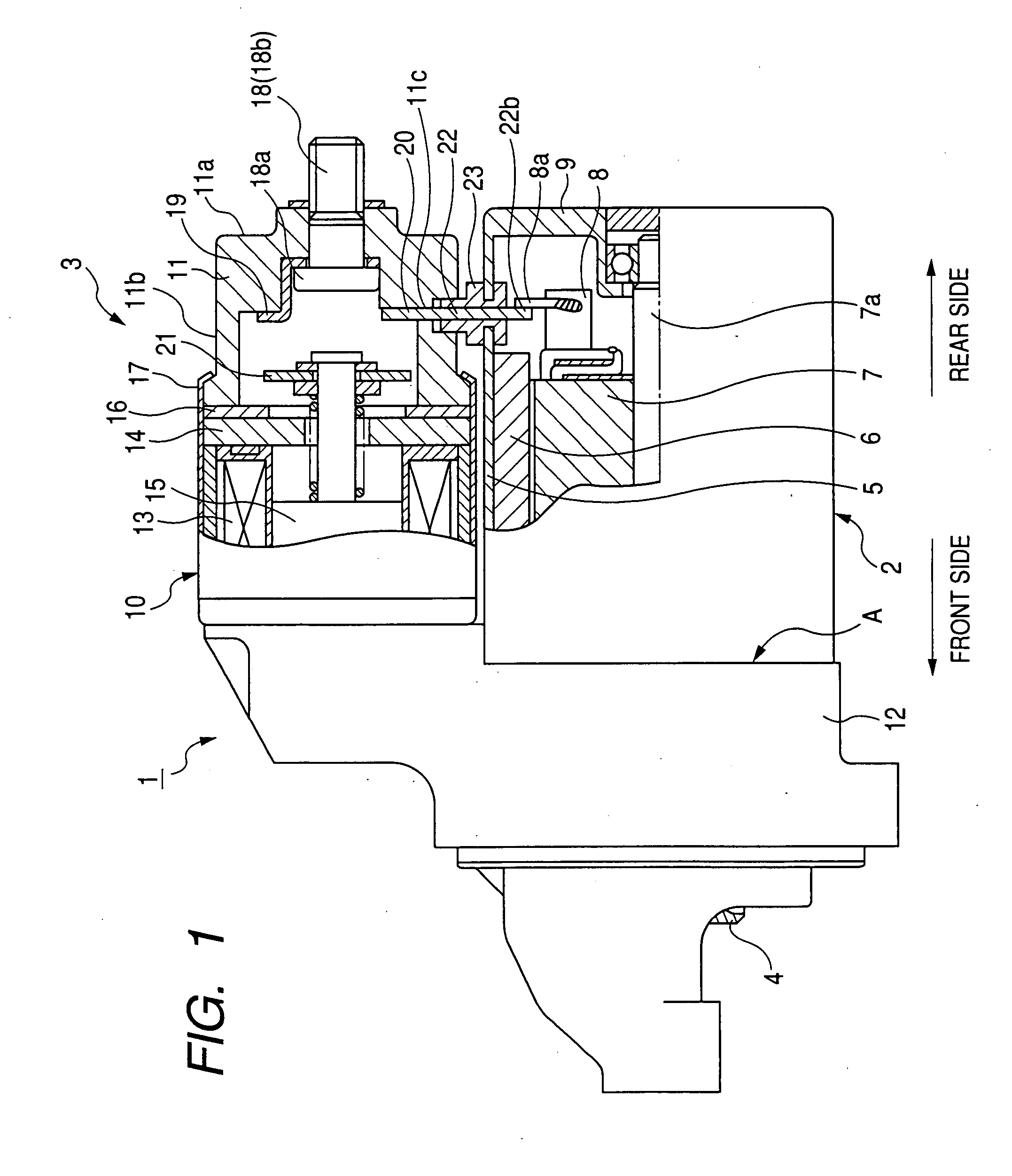
[0027]FIG. 1 shows the overall structure of a starter 1 according to the first embodiment of the invention. The starter 1 is designed to start an internal combustion engine of an automobile.

[0028]As shown in FIG. 1, the starter 1 includes a motor 2 working to generate torque, an electromagnetic switch 3 working to selectively open and close a circuit for supplying electric power to the motor 2 (to be referred to as motor circuit hereinafter), a pinion 4 configured to be rotated by the torque generated by the motor 2. The starter 2 starts the engine in such a manner well known in the art as to bring the pinion gear 4 into mesh with a ring gear (not shown) of the engine and thereby transmit the torque generated by the motor 2 from the pinion gear 4 to the ring gear.

[0029]The motor 2 includes a cylindrical yoke 5 for forming a magnetic circuit, permanent magnets 6 arranged on the inner periphery of the yoke 5 to create a magnetic field, an armature 7 disposed on the inner periphery of ...

second embodiment

[0054]This embodiment illustrates a starter 1A which has a structure almost identical to that of the starter 1 according to the first embodiment. Accordingly, only the differences between the starters 1 and 1A will be described hereinafter.

[0055]As shown in FIG. 4, the starter 1A further includes, compared to the starter 1, a connecting plate 28 that connects the metal plate 22, which makes up the M fixed contact 20, to the pigtail 8a of the positive brush 8.

[0056]More specifically, in the starter 1A, the first end portion of the metal plate 22 is inserted in the contacts cover 11 to form the M fixed contact 20. The second end portion 22b of the metal plate 22 is bent to extend in the axial direction of the motor 2, and thus is not inserted in the motor 2. In addition, a sealing member 29 is employed, instead of the grommet 23, to hermetically seal between the metal plate 22 and the contacts cover 11.

[0057]The connecting plate 28 is made of a conducive metal, such as copper, and is ...

third embodiment

[0062]This embodiment illustrates a starter 1B which has a structure almost identical to that of the starter 1 according to the first embodiment. Accordingly, only the differences between the starters 1 and 1B will be described hereinafter.

[0063]As shown in FIG. 5, the starter 1B includes a plurality of field coils 60, instead of the permanent magnets 6 as in the starter 1, to create the magnetic field.

[0064]Each of the field coils 60 has a first end 60a and a second end 60b. All the first ends 60a of the field coils 60 are connected to a connection bar 30 provided in the motor 2; all the second ends 60b of the field coils 60 are connected to the pigtail 8a of the positive brush 8.

[0065]Further, in the present embodiment, the second end portion 22b of the metal plate 22 is inserted in the motor 2 so as to be directly connected to the connection bar 30.

[0066]With the above configuration, the field coils 60 are electrically connected in series with the armature 7 of the motor 2.

[0067]...


PUM


Abstract

A starter includes a motor and an electromagnetic switch disposed close to and radially outward of the motor. The switch includes a contacts cover, a terminal bolt, and a conductive metal member. The contacts cover is cup-shaped. The terminal bolt is secured in the contacts cover so as to extend in the axial direction of the motor through an end wall of the contacts cover. The metal member has a first and a second end portion. The first end portion is inserted in the contacts cover through a side wall of the contacts cover. The second end portion is located outside the contacts cover and electrically connected to the motor. The switch further includes a movable contact, a first fixed contact that is electrically connected to a power source via the terminal bolt, and a second fixed contact made up of the first end portion of the metal member.

Description

CROSS-REFERENCE TO RELATED APPLICATION[0001]This application is based on and claims priority from Japanese Patent Application No. 2006-203057, filed on Jul. 26, 2006, the content of which is hereby incorporated by reference into this application.BACKGROUND OF THE INVENTION[0002]1. Technical Field of the Invention[0003]The present invention relates to a starter for starting an engine, which includes a motor and a minimized electromagnetic switch working to operate electric power supply to the motor.[0004]2. Description of the Related Art[0005]Conventionally, a starter for starting an engine generally includes a motor and an electromagnetic switch that is disposed close to and radially outward of the motor and works to operate main contacts of a motor circuit.[0006]More specifically, the electromagnetic switch includes a solenoid, a pair of fixed contacts that serve as the main contacts of the motor circuit, and a movable contact. The solenoid includes an electromagnetic coil and a pl...

Claims


Application Information

Patent Timeline
IPC IPC(8): H01H1/00
CPCF02N11/00H01H51/08H01H50/14F02N15/067F02N15/006
Inventor KURASAWA, TADAHIROANDOH, KAZUHIROUTSUNOMIYA, YAMATO
Owner DENSO CORP
Why Eureka
Try Eureka