Edge direction based image interpolation method

a technology of image interpolation and edge direction, applied in image enhancement, instruments, television systems, etc., can solve the problems of affecting the effectiveness and affecting the accuracy of edge direction detection, etc., to achieve the effect of effective detection and utilization of edge direction information

Inactive Publication Date: 2008-01-31
SAMSUNG ELECTRONICS CO LTD
View PDF29 Cites 25 Cited by
  • Summary
  • Abstract
  • Description
  • Claims
  • Application Information

AI Technical Summary

Benefits of technology

[0009] The present invention addresses the above needs. An object of the present invention is to provide an edge direction based image interpolation method that can effectively detect and utilize edge direction information without introducing obvious artifacts in the interpolated image. According to such a method, image edge direction is detected at the center position

Problems solved by technology

When there is a large scene change in the video, temporal information may not be reliable for de-interlacing.
However, one problem with this general type of spatial interpolation is the degradation of image edges, including serrate lines or blurred edges that may appear in the interpolated image.
However, it is still a difficult and open issue how to effectively and accurately dete

Method used


Image

  • Edge direction based image interpolation method
  • Edge direction based image interpolation method
  • Edge direction based image interpolation method

Examples


Embodiment Construction

[0021] While this invention is susceptible of embodiments in many different forms, there are shown in the drawings and will herein be described in detail, preferred embodiments of the invention with the understanding that the present disclosure is to be considered as an exemplification of the principles of the invention and is not intended to limit the broad aspects of the invention to the embodiments illustrated.

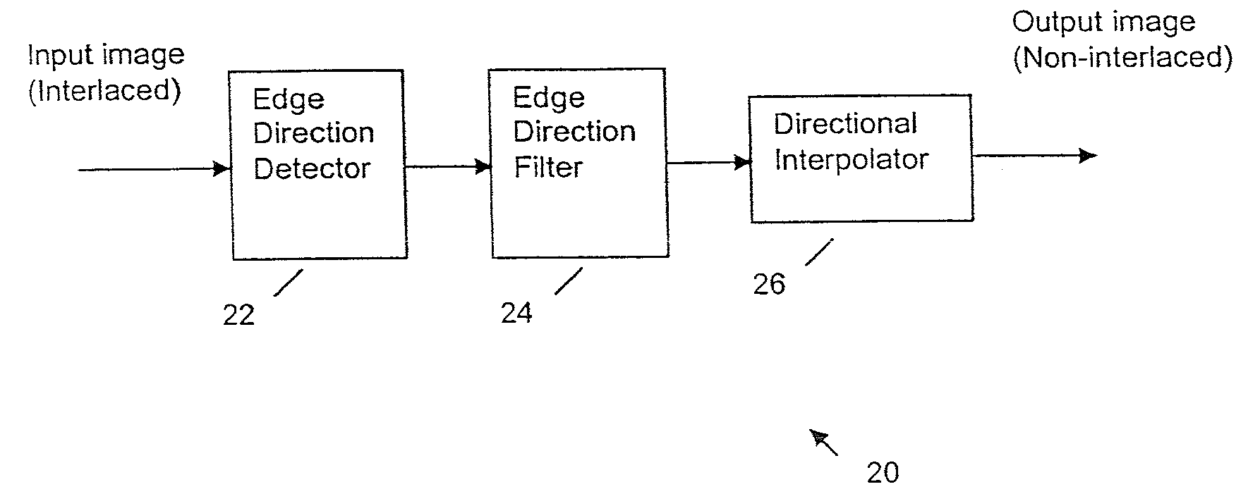
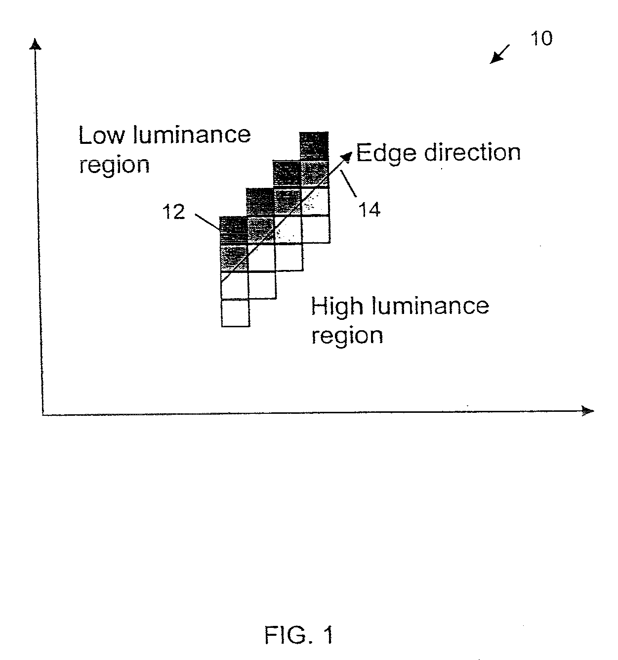
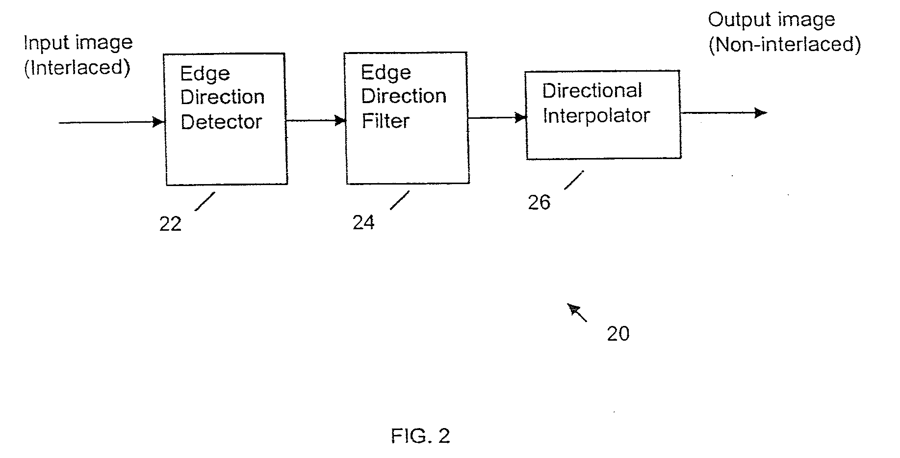
[0022] As noted above, in one embodiment the present invention provides an edge direction based image interpolation method, wherein image edge direction is detected at the center position of every two neighboring scan lines in an interlaced scan. All the directions detected in a given field constitute an edge orientation map. Edge directions are filtered to remove false and unreliable edge directions from the edge orientation map. If an edge direction is removed, the vertical edge direction is used to replace that direction in the edge orientation map.

[0023] For interpola...


PUM


Abstract

A method for interpolating pixel data of an omitted line by use of pixel data from an interlaced scan, for de-interlacing an interlaced video image. Image edge direction is detected at the center position of every two neighboring scan lines in an interlaced scan. All the directions detected in a given field constitute an edge orientation map. Edge directions are filtered to remove false and unreliable edge directions from the edge orientation map. If an edge direction is removed, the vertical edge direction is used to replace that direction in the edge orientation map. For interpolating a new pixel at the center of two neighboring scan lines, the corresponding direction for that position is used as the interpolation direction to calculate the value of the new pixel. If the direction is vertical, a filter is used along the vertical direction to calculate the interpolation value. If the direction is non-vertical, and has an integer value, then interpolation is performed by taking the average of the two neighboring sample values along the direction. If the direction is non-vertical and has a non-integer value, then an interpolation value is calculated using a directional bilinear method.

Description

FIELD OF THE INVENTION [0001] The present invention relates to image interpolation, and in particular, to detecting edge directions between two neighboring lines in an interlaced scan and interpolating an omitted line between the two lines along the detected edge directions. BACKGROUND OF THE INVENTION [0002] De-interlacing is a process for converting an interlaced scan into a non-interlaced scan. Such a function is necessary in digital TV systems where the input video may have many different video formats. If a digital TV monitor is non-interlaced and the input video is in an interlaced format, the video needs to be de-interlaced. [0003] Detecting edge directions (orientations) between neighboring lines in an interlaced scan is important in de-interlacing. Along the edge direction, image pixels' luminance values remain constant or change gradually. However, across the edge direction, pixels' luminance values change sharply. [0004] There are existing methods for image de-interlacing...

Claims


Application Information

Patent Timeline
IPC IPC(8): H04N7/01G06T5/00G06T5/20
CPCG06T2207/10016G06T7/0085G06T3/403G06T7/13G06T5/20
Inventor WANG, XIANGLINKIM, YEONG-TAEG
Owner SAMSUNG ELECTRONICS CO LTD
Why Eureka
Try Eureka