Magnetic head and magnetic disc drive
- Summary
- Abstract
- Description
- Claims
- Application Information
AI Technical Summary
Benefits of technology
Problems solved by technology
Method used
Image
Examples
first embodiment
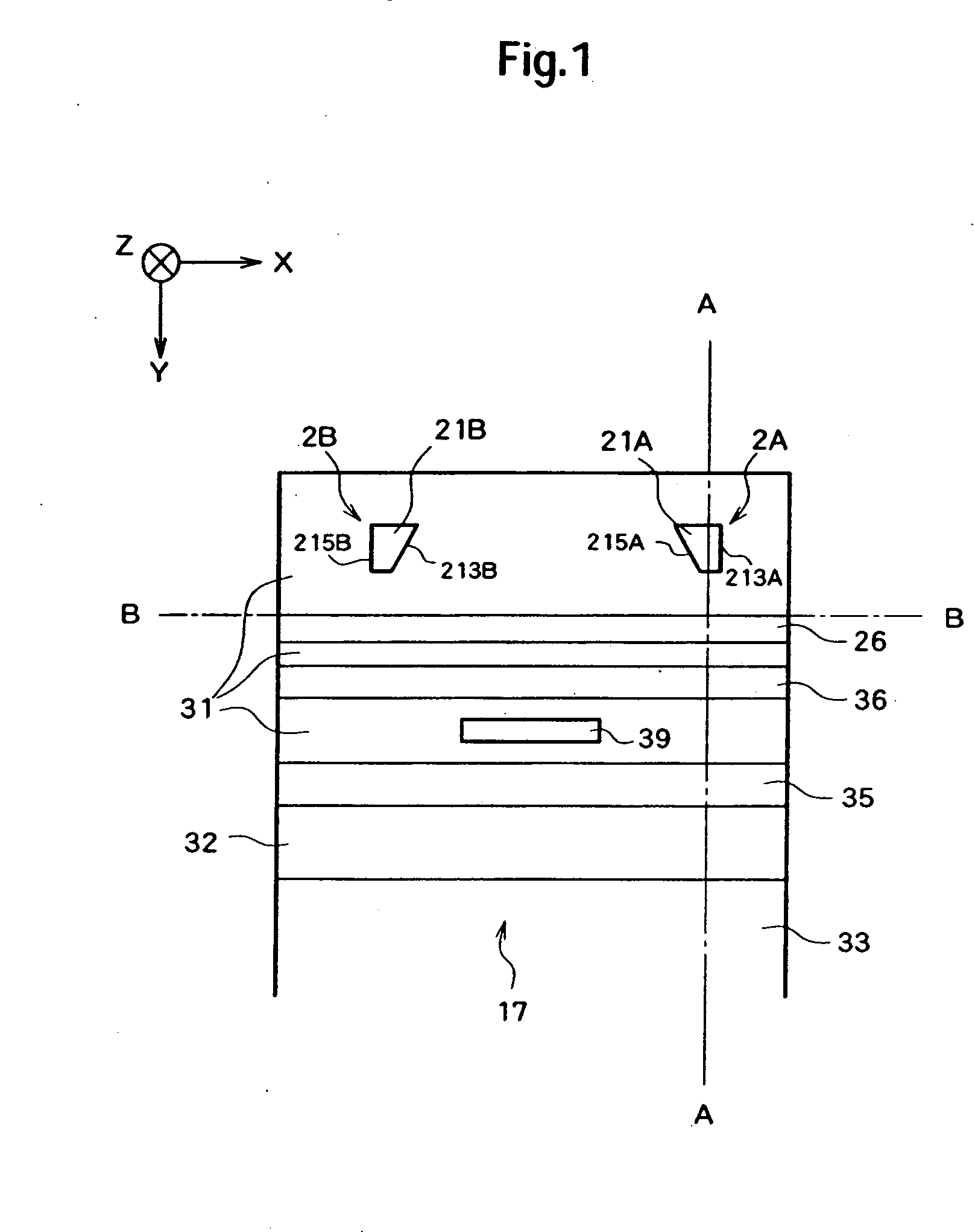
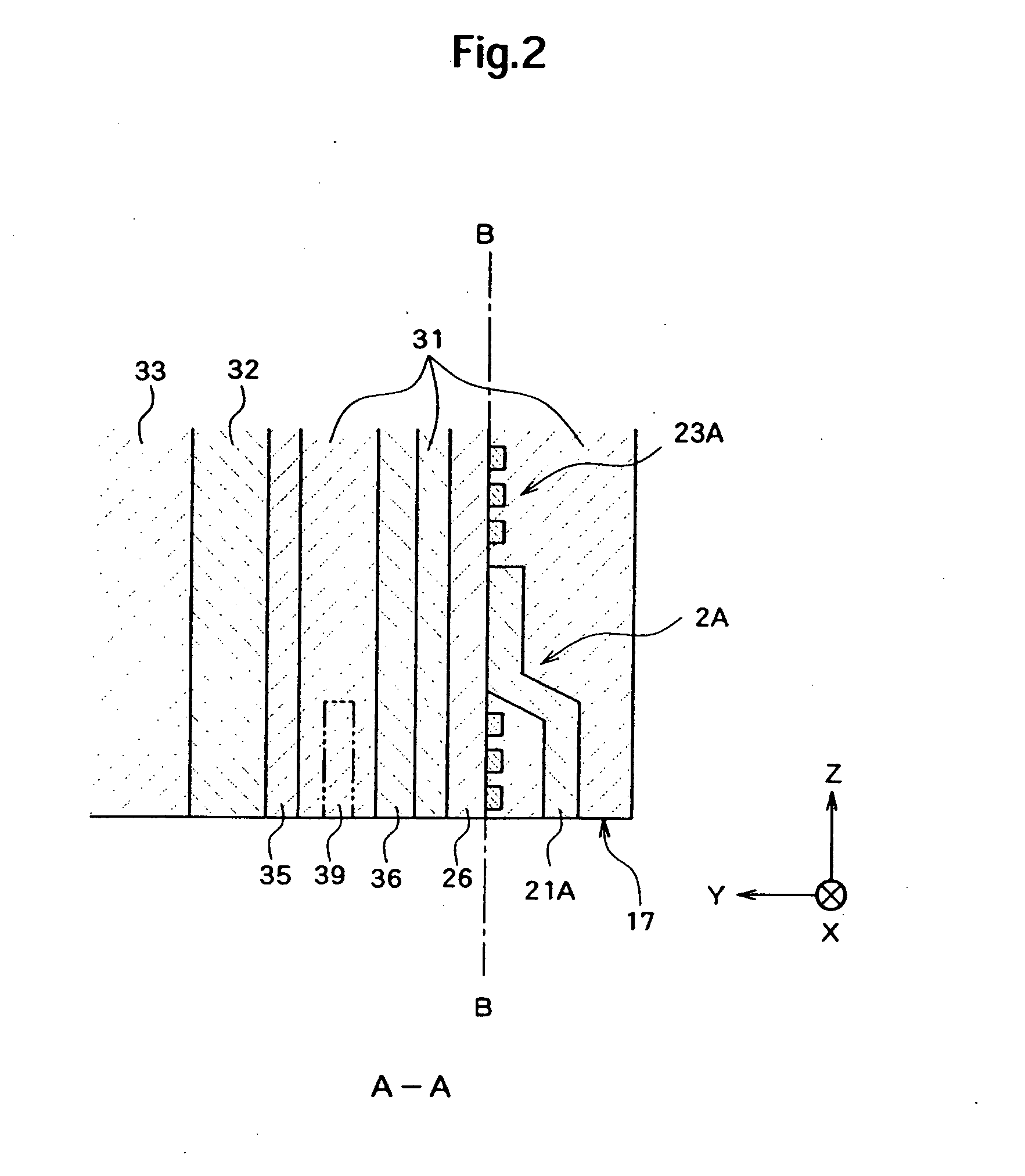
[0033] Hereinafter, a magnetic head will be described. FIG. 1 is a diagram illustrating an air-bearing surface 17 (the surface opposed to a recording surface of a magnetic disc) of a magnetic head 11. FIG. 2 is a sectional view taken along the A-A line in FIG. 1. FIG. 3 is a sectional view taken along the B-B line in FIG. 1. Here, the Y direction is a rotational radius direction when the magnetic head 11 is rotated and the positive direction thereof is a direction toward the rotation axis. The Z direction is a direction perpendicular to the recording surface of the magnetic disc and the positive direction thereof is a direction of the flying movement of the magnetic head 11.
[0034] The magnetic head 11 is configured as a thin film magnetic head adopting a perpendicular magnetic recording system. As shown in FIG. 4, the magnetic head 11 is attached onto the slider 91 and is rotated substantially along the radius direction of the recording surface in the state where the magnetic head 1...
second embodiment
[0054] a magnetic head will now be described. FIG. 8 illustrates an air-bearing surface 17 (the surface faces to a recording surface of a magnetic disc) of a magnetic head 12. FIG. 9 is a sectional view taken along the C-C line in FIG. 8.
[0055] In the magnetic head 12, a first write element 2A and a second write element 2B are disposed on layers different from each other (the write elements are arranged in the Y direction). Here, an upper side is defined as a lamination direction in the layer structure, that is, the negative Y direction. On a read shield layer 36, a return pole layer 26A is disposed, and the first write element 2A is provided on the return pole layer 26A. A return pole layer 26B is also disposed thereon with a read shield layer 37 interposed therebetween. The second write element 2B is provided on the return pole layer 26B. The first write element 2A and the second write element 2B in both the X direction and the Y direction may be arbitrarily chosen. Additionally, ...
third embodiment
[0058] a magnetic head will now be described. FIG. 10 is a diagram illustrating an air-bearing surface 17 (which faces to a recording surface of a magnetic disc) of a magnetic head 13.
[0059] In the magnetic head 13, a return pole layer 26 is disposed on the read shield layer 36, and a first write element 2A, a second write element 2B, and a third write element 2C are provided on the same layer which is the return pole layer 26 (the write elements are arranged in the X direction). Here, an upper side is defined as a lamination direction in the layer structure, that is, the negative Y direction. The third write element 2C has the same configuration as the first write element 2A and the second write element 2B. It is possible to change positions of the first write element 2A, the second write element 2B, and the third write element 2C in the X direction. It is also possible to change positions of them in the Y direction.
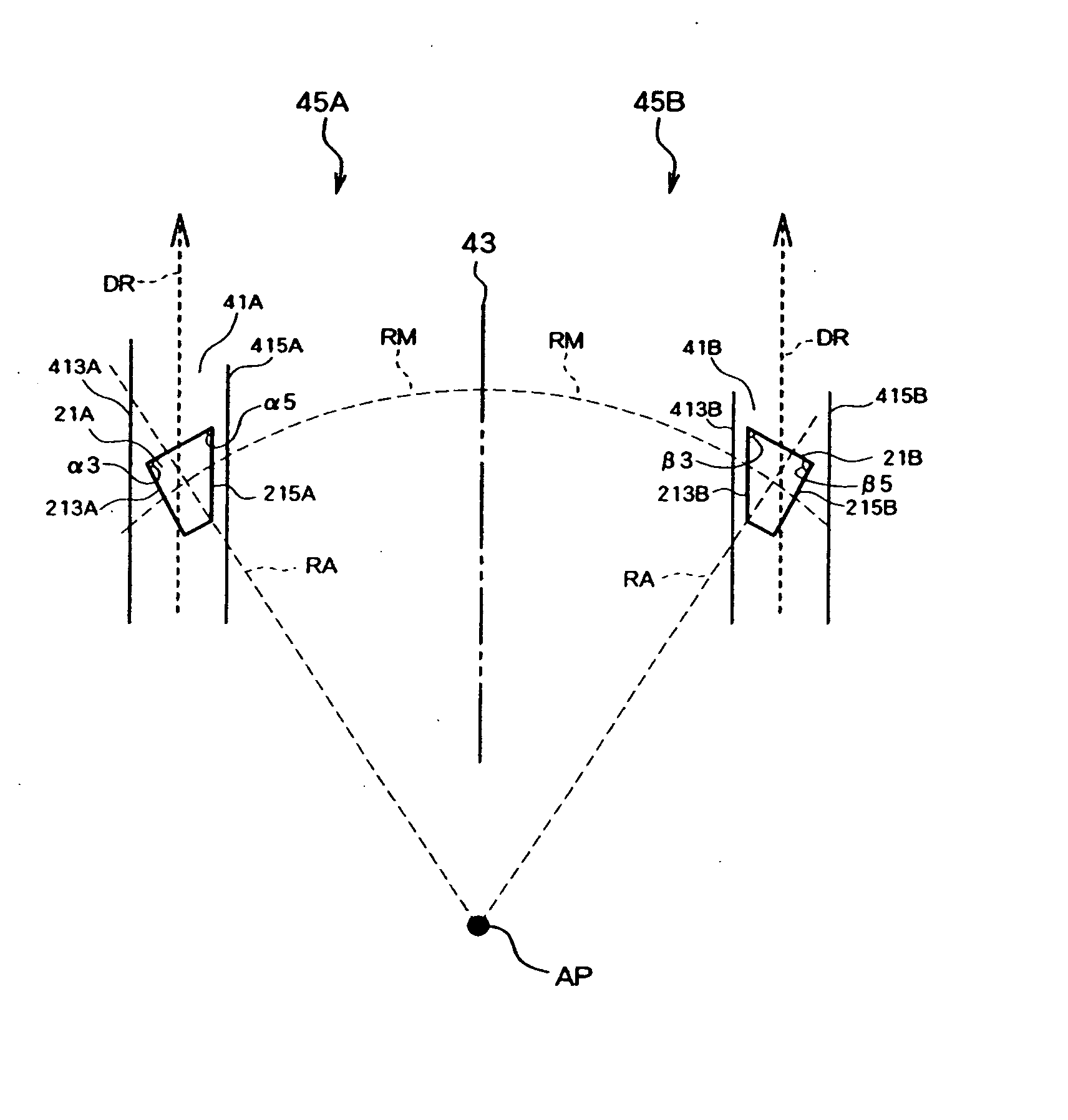
[0060]FIG. 11 is a diagram illustrating a relationship between a ...
PUM
 Abstract
Description
Claims
Application Information
 - R&D
- Intellectual Property
- Life Sciences
- Materials
- Tech Scout
- Unparalleled Data Quality
- Higher Quality Content
- 60% Fewer Hallucinations
Browse by: Latest US Patents, China's latest patents, Technical Efficacy Thesaurus, Application Domain, Technology Topic, Popular Technical Reports.
© 2025 PatSnap. All rights reserved.Legal|Privacy policy|Modern Slavery Act Transparency Statement|Sitemap|About US| Contact US: help@patsnap.com


