
Adhesive-Less DC Bus System and Method for Manufacturing

a dc bus and adhesive-less technology, applied in the direction of laminated bus bars, electrical apparatus casings/cabinets/drawers, coupling device connections, etc., can solve the problems of high cost, inconvenient operation, and insufficient consumption of power delivered from a power source or supply

Inactive Publication Date: 2008-01-31
ROCKWELL AUTOMATION TECH
View PDF7 Cites 12 Cited by
  • Summary
  • Abstract
  • Description
  • Claims
  • Application Information

AI Technical Summary

Benefits of technology

[0017]In accordance with still another aspect of the invention, a clamping fastener for creating an adhesive-less power bus assembly is disclosed that includes a first clamping plate configured to be arranged within a through hole formed in a power bus assembly and a flange axially offset from the first clamping plate and extending radially from the first clamping plate to extend over a portion of a first side of the power bus assembly. The clamping fastener also includes a second clamping plate configured to be arranged within the through hole in the power bus

Problems solved by technology

Often, power delivered from a power source or supply is not properly conditioned for consumption.
While such manufacturing methods have long been employed to great success with meeting the structural requirements needed to withstand vibrations and temperature changes associated with a wide variety of environments, they are rather costly.
As such, the cost of more complex bus structures is often prohibitive.
For example, a “3D” bus structure, where the bus sheets are bent to extend into multiple planes, is often cost prohibitive because the process of correctly aligning and gluing adjacent layers simultaneously across multiple planes is extremely difficult, if not impossible.

Method used


Image

  • Adhesive-Less DC Bus System and Method for Manufacturing
  • Adhesive-Less DC Bus System and Method for Manufacturing
  • Adhesive-Less DC Bus System and Method for Manufacturing

Examples


Embodiment Construction

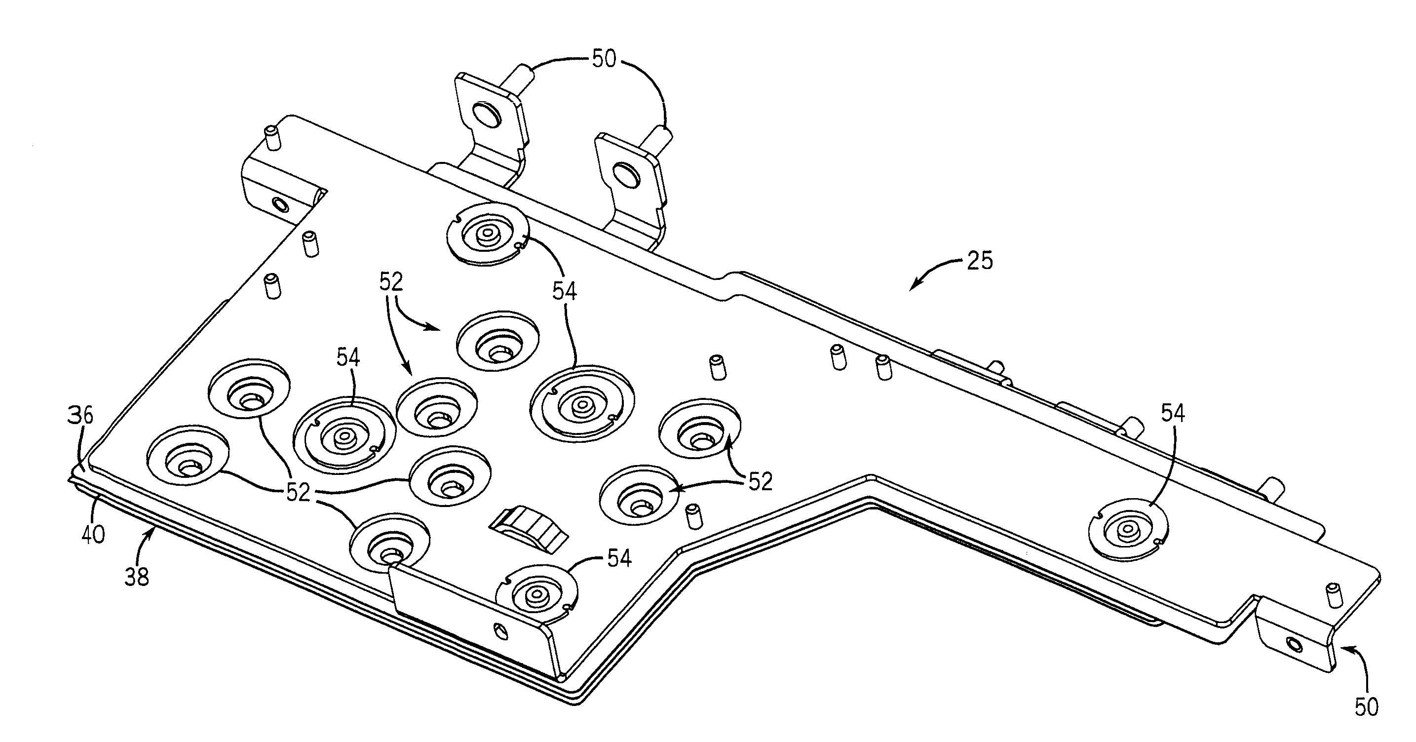
[0027]While the following description is directed a motor drive system 10, it is contemplated that the following power bus system can be used with a wide variety of associated systems. For example, it is contemplated that the power bus may be used with vehicular power systems, such as hybrid vehicle systems.

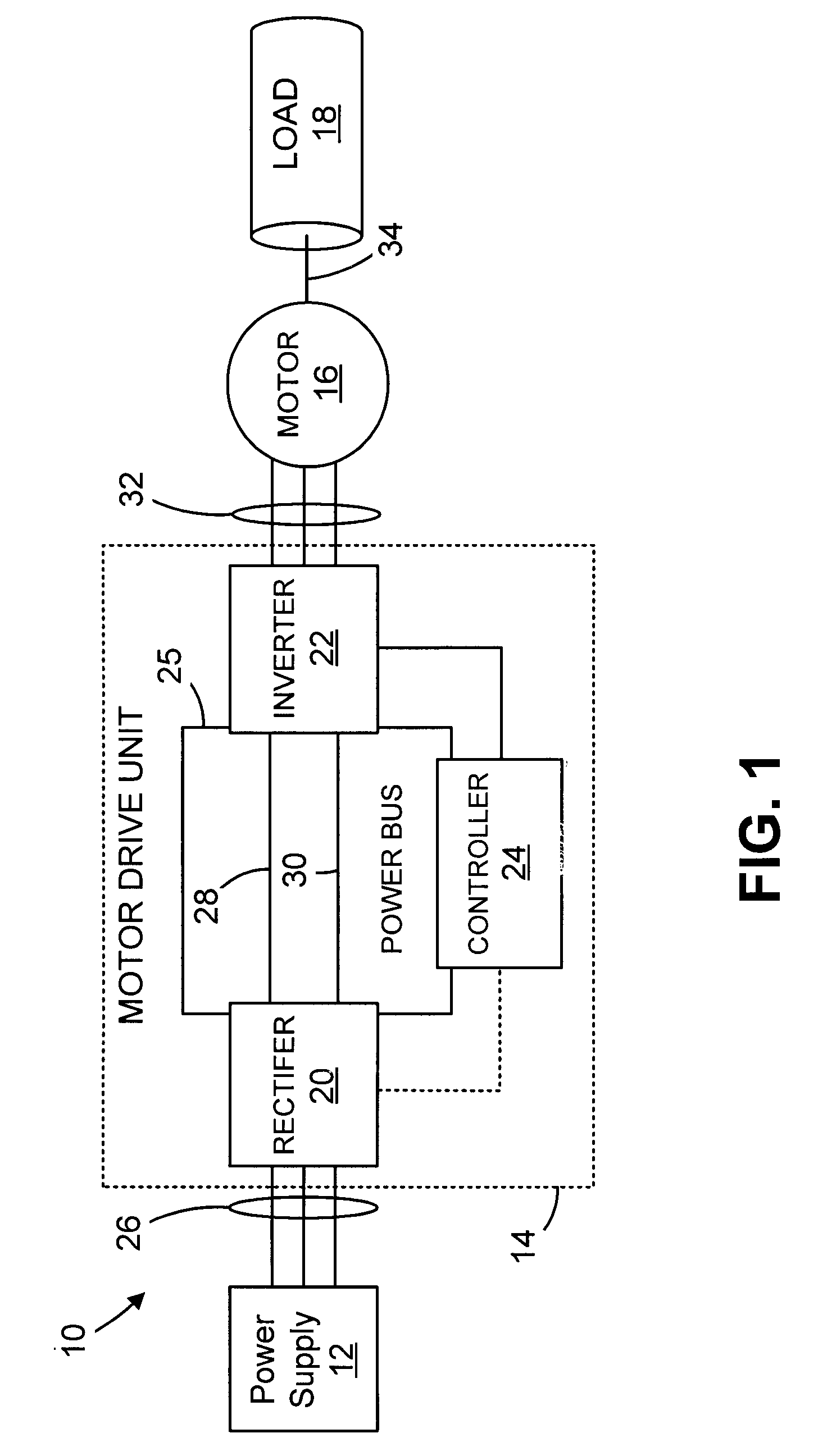
[0028]Referring now to FIG. 1, the present invention can be described in the context of a motor control system 10. The motor control system 10 includes a power supply 12 and a motor drive unit 14. The power supply 12 provides power to the motor drive unit 14 that, in turn, converts the power to a more usable form for a three-phase motor 16 that drives an associated load 18.

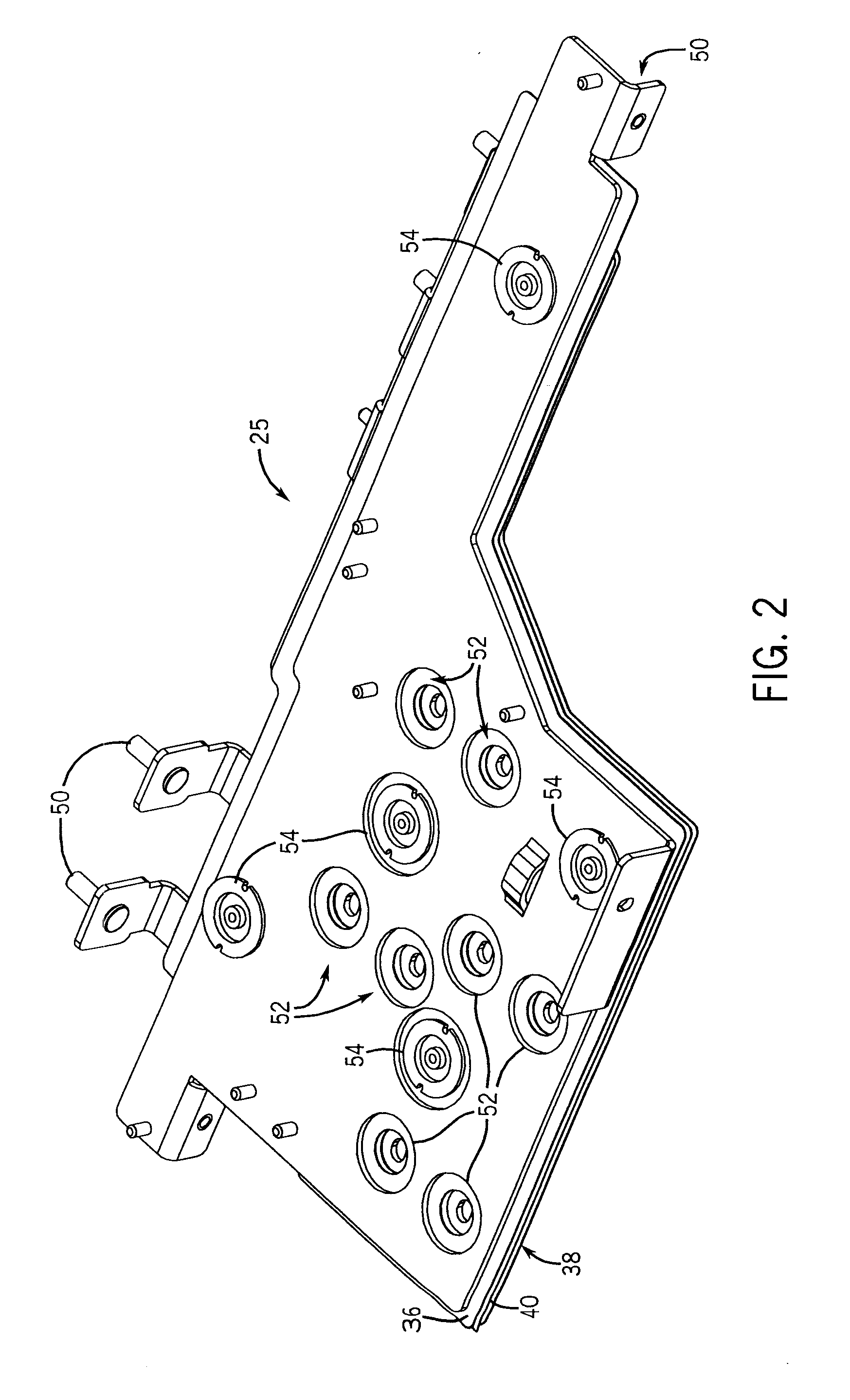
[0029]The motor drive unit 14 includes a variety of components, such as a rectifier 20, an inverter 22, and a controller 24, each of which are connected to a power bus 25. During operation, the power supply 12 provides three-phase AC power, for example, as received from a utility grid over transmission power li...


PUM


Abstract

A system and method for manufacturing a power bus assembly is provided. The power bus assembly includes a first conductive sheet configured to receive a positive charge and distribute the positive charge to a plurality of connection points formed thereon. The power bus assembly also includes a second conductive sheet configured to receive a negative charge and distribute the negative charge to a plurality of connection points formed thereon. Additionally, the power bus assembly includes an insulating sheet arranged between the first conductive sheet and the second conductive sheet to electrically isolate the first conductive sheet from the second conductive sheet. A plurality of vice fasteners are included to secure the first conductive sheet, the second conductive sheet, and the insulating sheet together to form the power bus assembly.

Description

CROSS-REFERENCE TO RELATED APPLICATIONS[0001]Not applicable.STATEMENT REGARDING FEDERALLY SPONSORED RESEARCH OR DEVELOPMENT[0002]Not applicable.BACKGROUND OF THE INVENTION[0003]The present invention relates generally to power bus systems and, more particularly, to a bus assembly for DC bus links used in motor drive units and the like that can be assembled using a plurality of clamping fasteners. The clamping fasteners are designed to secure the multiple layers of the DC bus together without the need for adhesives.[0004]Often, power delivered from a power source or supply is not properly conditioned for consumption. For example, power plants are linked to power consuming facilities (e.g., buildings, factories, etc.) via utility grids that are designed to be extremely efficient at delivering massive amounts of power. To facilitate efficient distribution, power is delivered over long distances as fixed frequency three-phase alternating current (AC) power. Similarly, in modern vehicle s...

Claims


Application Information

Patent Timeline
IPC IPC(8): H02B1/00
CPCH02G5/005
Inventor KEEGAN, JEREMY J.DAY, SCOTT D.SIEBERT, WILLIAM K.
Owner ROCKWELL AUTOMATION TECH
Learn More