Apparatus and Method for Solid-Liquid Contact

a technology of solid-liquid contact and apparatus, which is applied in the direction of transportation and packaging, rotary stirring mixers, chemical/physical/physicochemical processes, etc., can solve the problems of deteriorating contact efficiency, difficult to achieve good compatibility between them, and inability to provide good contact efficiency as expected, so as to improve improve the rectification region. , the effect of improving the solid-liquid contact efficiency

Active Publication Date: 2008-01-31
KUREHA KAGAKU KOGYO KK
View PDF70 Cites 18 Cited by
  • Summary
  • Abstract
  • Description
  • Claims
  • Application Information

AI Technical Summary

Benefits of technology

[0013] A principal object of the present invention is to provide a continuous multi-stage stirring chamber-type solid-liquid contact apparatus exhibiting a high contact efficiency.
[0014] Another object of the present invention is to provide a solid-liquid contact apparatus which allows a high uniformity of solid and liquid flows and has a simple structure allowing an easy scale-up.
[0017] In the solid-liquid contact apparatus of the present invention, each stirring chamber is constructed vertically asymmetrically, and each stirring chamber is provided with a lower stirring region functioning to improve the solid-liquid contact efficiency and an upper rectification region, thereby having succeeded in improving the solid-liquid contact efficiency while preventing the back mixing of axial flows.
[0018] Further, the solid-liquid contact method of the present invention is characterized by performing solid-liquid contact in the above-mentioned solid-liquid contact apparatus, while stirring a solid-liquid mixture at a Reynolds number in a range of 500 to 500,000 and supplying a solid flow at a load ratio of at least 60% with respect to a maximum load of the apparatus. The method is based on an experimental result that the solid-liquid contact efficiency is improved as the load ratio is increased (as shown in Examples described hereinafter).

Problems solved by technology

On the other hand, however, a better mixing is liable to be accompanied with back mixing in the direction of solid and liquid flow axes which remarkably deteriorate the contact efficiency, so that it is difficult to attain a good compatibility there between.
In order to reduce the back mixing while maintaining a good solid-liquid mixing state, there has been known a method of partitioning a flow path in a chamber with partitioning plates into a plurality of chambers forming a multiple stage, but this cannot provide a good contact efficiency as expected since back mixing is also caused by countercurrent flows between the respective chambers.
It is also effective for reducing the back mixing to reduce the sectional area of the flow path between the respective chambers, but this is accompanied with a reduction of treatment capacity and is therefore not practical.
However, according to this type of apparatus, the flows in the settler section are liable to cause a non-uniform portion, and as a result, it becomes difficult to uniformize the treatment on the solid side, so that this type of apparatus is unsuitable as apparatus for operations, particularly for providing an objective product on the solid side, such as washing and impregnation.
In addition to the above, for solid-liquid extraction operation, there has been generally adopted a type of apparatus including a conveyer, such as a belt, baskets or a screw for forming a solid moving layer, and moving a liquid as a counter-current flow on a crossing stream respectively penetrating through the solid moving layer, but a uniform treatment on the solid side is difficult thereby, thus leaving a problem as an apparatus particularly for operations, such as washing and impregnation, for providing a solid objective product.

Method used


Image

  • Apparatus and Method for Solid-Liquid Contact
  • Apparatus and Method for Solid-Liquid Contact
  • Apparatus and Method for Solid-Liquid Contact

Examples


example 1

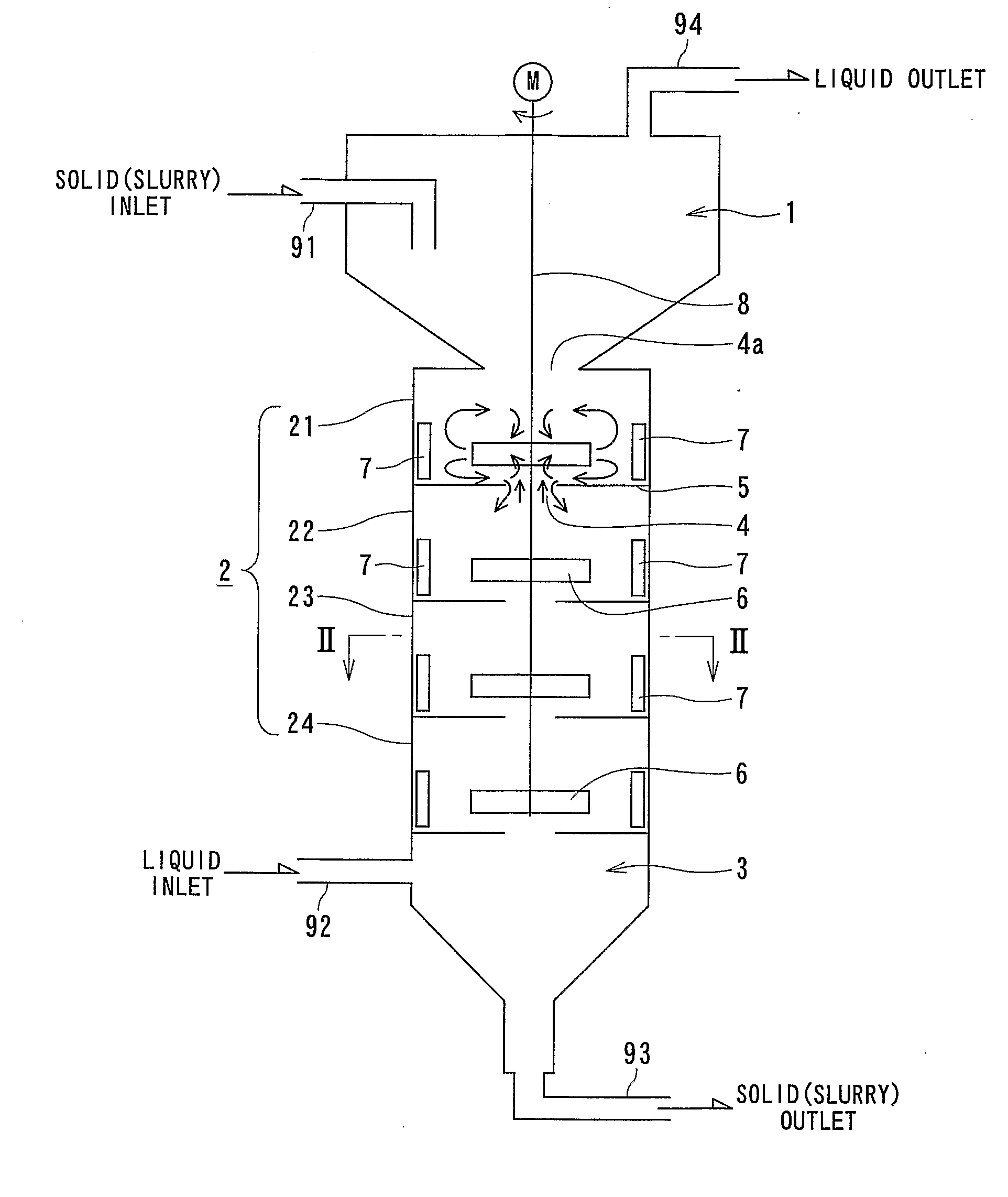
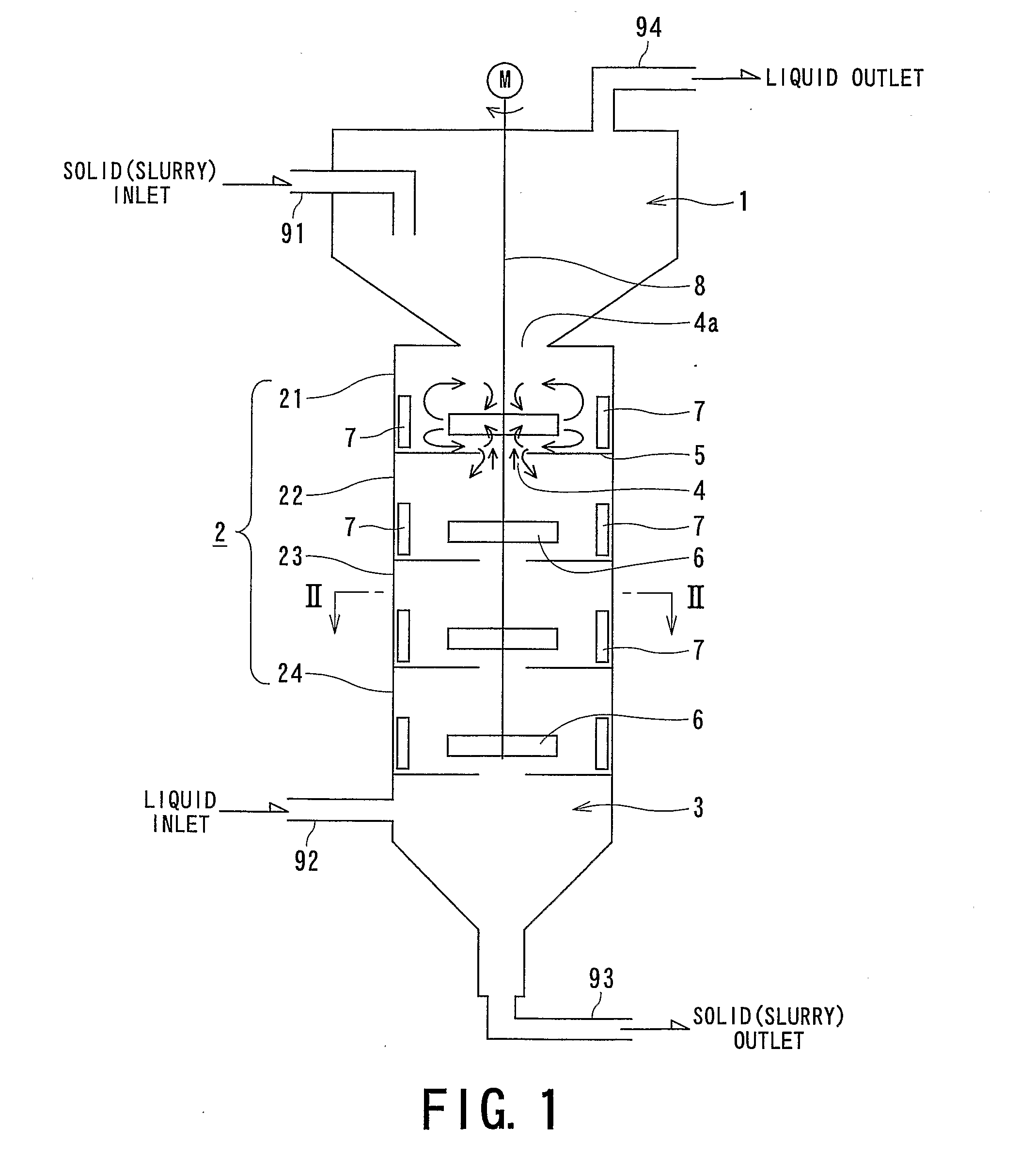
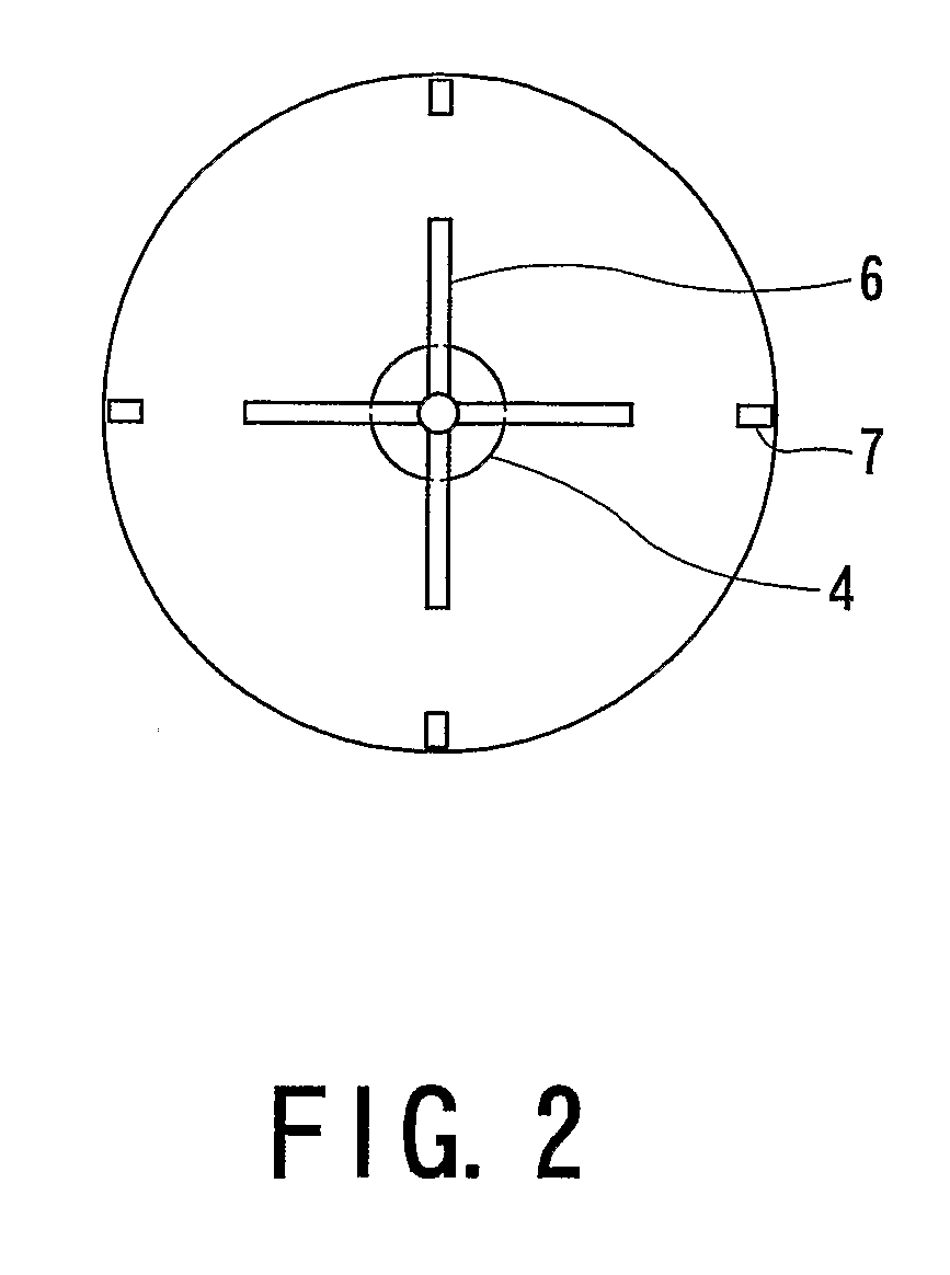
[0061] In a solid-liquid contact apparatus having an organization shown in FIG. 1 (and FIG. 2), a PPS (polyphenylene sulfide) slurry was supplied at a rate of 25 kg / h through a pipe 91 and water was supplied as a washing liquid at a rate of 37.5 kg / h from the pipe 92 to effect a continuous solid-liquid contact treatment. The treatment flow rate or load of the apparatus was 62.5 kg / h as a total of the slurry and water supply rates. The PPS slurry contained 5 kg / h of PPS particles (on a dry basis), 16 kg / h of water and 4 kg / h of acetone, so that the liquid excluding the PPS particles in the slurry contained 20 wt. % of acetone (acetone concentration in the slurry of 16 wt. %) and the concentration of the PPS particles in the slurry was 20 wt %. Further, a washing bath ratio L / P determined as a ratio of the washing liquid to the PPS particles in the slurry was 7.5 (=37.5 / (25×0.2).

[0062] The apparatus had 4 stirring chambers 21-24 which were made of an acrylic resin sheet and allowed s...

reference example 1

[0085] While the stirring conditions and the washing bath ratio (L / P=7.5) of Example 1 were retained, the treatment load (as a total of the slurry supply rate to the pipe 91 and the water supply rate to the pipe 92) was reduced down to 37.5 kg / h (3 kg / h as PPS particles). As a result, the outlet acetone concentration was 0.60 wt. % and the average stirring Reynolds number Re in the apparatus was 6.82×10³. The treatment load of 37.5 kg / h corresponds to 57% of the maximum load.

reference example 2

[0086] In Reference Example 1, the blade rotation speed was reduced down to 4 rpm, which corresponded to an average stirring Reynolds number Re in the apparatus of 1.37×10². Under the stirring condition and while retaining the washing bath ratio (L / P=7.5), the treatment load (as a total of the slurry supply rate to the pipe 91 and the water supply rate to the pipe 92) was set at 37.5 kg / h (3 kg / h as the PPS particles). As a result, the outlet acetone concentration was 1.40 wt. %.

[0087] Incidentally, in the above apparatus, the slurry supply rate to the pipe 91 and water supply rate to the pipe 92 were gradually increased, while retaining the washing bath ratio L / P=7.5, up to a treatment load (as a total of the slurry and water supply rates) of 40 kg / h, when the slurry discharge rate from the pipe 93 was not increased any more but stagnation of solid in the stirring chambers was observed in response to a further increase of the supply rates, so that 40 kg / h was taken as the maximum ...


PUM

PropertyMeasurementUnit
viscosityaaaaaaaaaa
viscosityaaaaaaaaaa
inner diameteraaaaaaaaaa

Abstract

A vertical solid-liquid contact apparatus, comprising: a plurality of stirring chambers disposed vertically adjacent to each other in series, a plurality of partitioning plates each partitioning an adjacent pair of the stirring chambers and provided with a communicating hole for communication between the adjacent pair of the stirring chambers, and a liquid inlet and a solid inlet provided at an upper part and a lower part of the apparatus. Each stirring chamber has an inner side wall defining the stirring chamber, a radially ejecting stirring blade, and at least one baffle fixed on the inner side wall so as to extend vertically. The stirring blade and the baffle are positionally biased to a lower side of the stirring chamber. The apparatus exhibits a good uniformity of solid-liquid flows and a high contact efficiency, is also simple in structure and allows easy scale-up. The apparatus can be widely applied to unit operations in the chemical industry. The apparatus exhibits a particularly good solid-liquid contact efficiency when operated in the neighborhood of its maximum load.

Description

TECHNICAL FIELD [0001] The present invention relates to a solid-liquid contact apparatus for contacting a solid and a liquid to effect an operation, such as washing, purification, extraction, impregnation or dissolution, practiced principally in the filled of chemical industry; particularly a continuous multi-stage stirring-type solid-liquid contact apparatus exhibiting a high solid-liquid contact efficiency and a solid-liquid contact method using the apparatus. BACKGROUND ART [0002] Hitherto, a countercurrent continuous contact scheme showing a high contact efficiency has been recognized to be advantageous as a method for solid-liquid contact treatment, i.e., a contact treatment between a solid or solid particles in a slurry and a treatment liquid. In order to effect a uniform and high-efficiency treatment with a small amount of solid-liquid contact, it is desirable to remove a dead zone or a short path for respective streams and improve the solid-liquid mixing so as to promote the...

Claims


Application Information

Patent Timeline
Patent Type & Authority Applications(United States)
IPC IPC(8): B01F7/16B01F3/14B01F27/906B01F23/57
CPCB01F13/1016B01F3/1221B01F13/1013B01F7/186B01F7/00633B01F23/53B01F27/191B01F27/9021B01F33/81B01F33/811B01F23/57B01F27/80
Inventor OHASHI, HIROAKIYUTAKA, IGARIMASANORI, KOBAYASHIKENTARO, OTAWARA
Owner KUREHA KAGAKU KOGYO KK
Why Eureka
Try Eureka