Method for video decoder memory reduction

a video decoder and memory reduction technology, applied in the field of video decoding, can solve the problems of cost and size of the memory used to buffer pictures in the decoding process, and the conventional solution is far from optimal in terms, so as to reduce the size of the decoded picture buffer, minimize potential drift and/or error, and minimize the effect of potential dri

Active Publication Date: 2008-01-31
AVAGO TECH INT SALES PTE LTD
View PDF5 Cites 30 Cited by
  • Summary
  • Abstract
  • Description
  • Claims
  • Application Information

AI Technical Summary

Benefits of technology

[0004]The objects, features and advantages of the present invention include providing a method for video decoder memory reduction that may (i) reduce a size of a decoded picture buffer, (ii) minimize potential drift and / or error due to resolution reduction of reference pictures, (iii) minimize potential drift and / or error due to missing reference pictures and / or (iv) provide a better tradeoff of a memory size versus a decoded video quality compared with conventional techniques.

Problems solved by technology

As the market for video decoders matures, a cost and size of the memory used to buffer pictures in the decoding process is becoming an important factor.
However, the conventional solutions are far from optimal in terms of a quality versus a memory tradeoff for an H.264-compliant decode.

Method used


Image

  • Method for video decoder memory reduction
  • Method for video decoder memory reduction
  • Method for video decoder memory reduction

Examples


Embodiment Construction

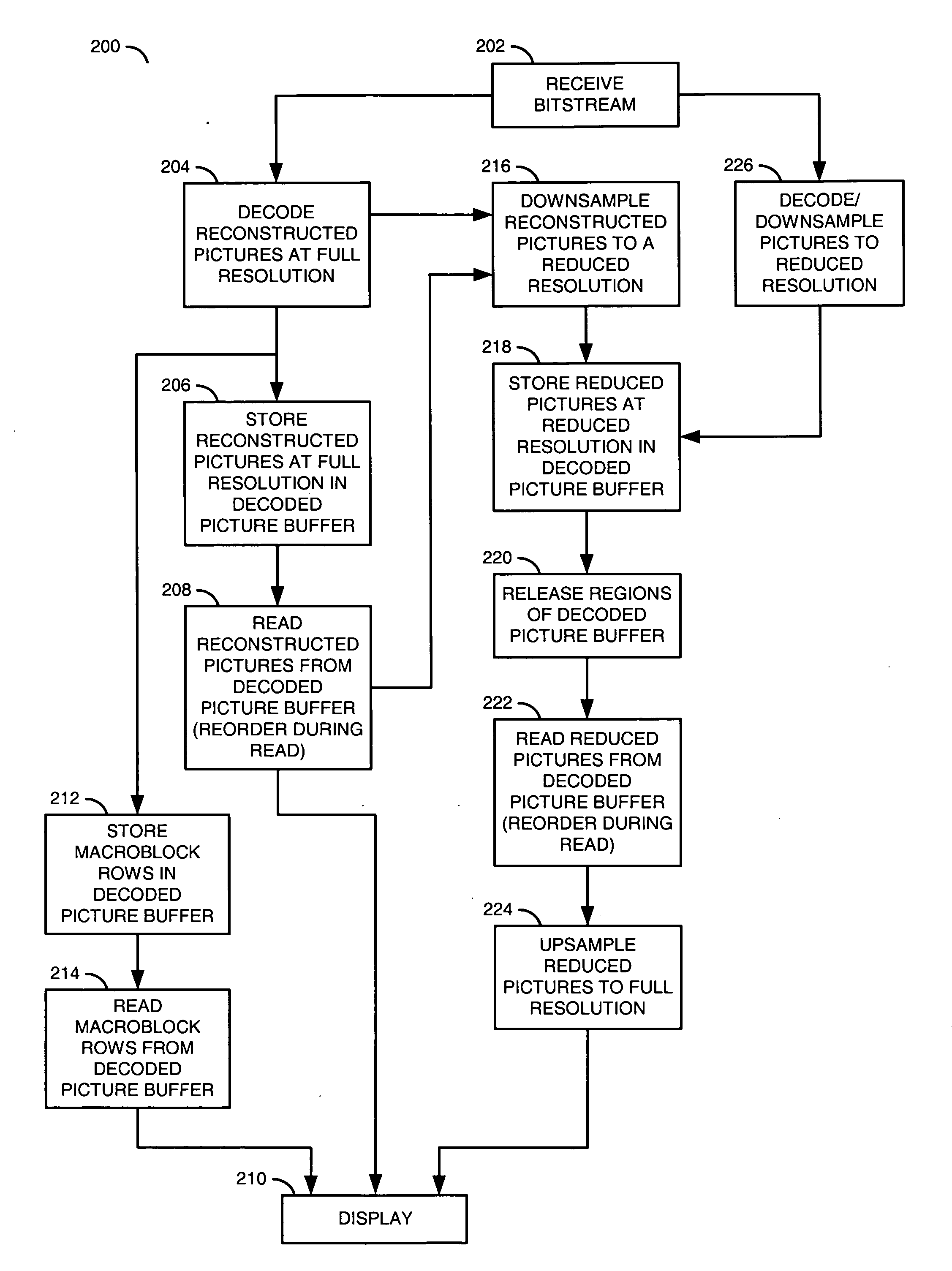
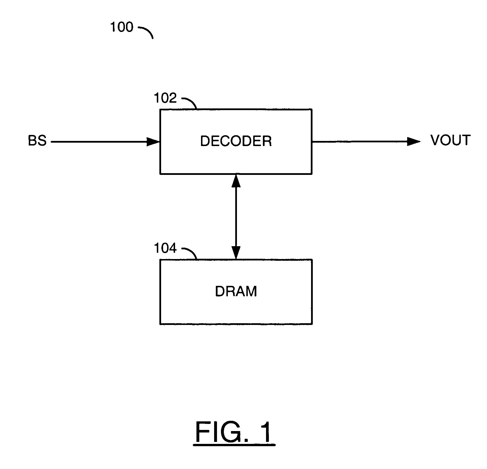
[0027]Referring to FIG. 1, a block diagram of a circuit 100 is shown in accordance with a preferred embodiment of the present invention. The circuit (or system) 100 may be referred to as a media processor circuit. The media processor circuit 100 generally comprises a circuit (or module) 102 and a circuit (or module) 104. An input signal (e.g., BS) may be received by the circuit 102. An output signal (e.g., VOUT) may be generated and presented by the circuit 102. The circuit 102 and the circuit 104 may be in communication with each other to exchange data.

[0028]The signal BS may be a compressed video signal, generally referred to as a bitstream. The signal BS may comprise a sequence of progressive-format frames and / or interlace-format fields. The signal BS may be compliant with a VC-1, MPEG and / or H.26x standard. The MPEG / H.26x standards generally include H.261, H.264, H.263, MPEG-1, MPEG-2, MPEG-4 and H.264 / AVC. The MPEG standards may be defined by the Moving Pictures Expert Group, I...


PUM


Abstract

A method for video decoding is disclosed. The method generally includes the steps of (A) decoding a first picture from a bitstream, the first picture having a first resolution, (B) storing the first picture at the first resolution in a memory and (C) storing the first picture at a second resolution in the memory, wherein the second resolution is lower than the first resolution.

Description

FIELD OF THE INVENTION[0001]The present invention relates to video decoding generally and, more particularly, to a method for video decoder memory reduction.BACKGROUND OF THE INVENTION[0002]As the market for video decoders matures, a cost and size of the memory used to buffer pictures in the decoding process is becoming an important factor. Conventional techniques used to reduce the decoding memory for MPEG-2 compliant bitstreams are (i) dropping B-frames and (ii) storing reference frames at a reduced resolution. However, the conventional solutions are far from optimal in terms of a quality versus a memory tradeoff for an H.264-compliant decode. Unlike MPEG-2 and other prior standards, the H.264 decode permits (i) multiple reference frames, (ii) mandatory storage of non-reference pictures for reordering delay only (and not for use as references), (iii) very flexible picture patterns (i.e., Groups of Pictures), (iv) hierarchical Groups of Pictures and (v) reference B-frames.SUMMARY O...

Claims


Application Information

Patent Timeline
Patent Type & Authority Applications(United States)
IPC IPC(8): H04N11/02H04N7/12
CPCH04N19/44H04N19/42H04N19/59H04N19/426H04N19/428H04N19/423H04N19/156H04N19/105H04N5/92
Inventor WINGER, LOWELL L.
Owner AVAGO TECH INT SALES PTE LTD
Why Eureka
Try Eureka