
System and method for reduction of speckle noise in an image

a speckle noise and image technology, applied in image enhancement, image analysis, instruments, etc., can solve the problems of high susceptibility, signal-dependent and grainy speckle noise formation, impede the efficiency of aerial data collection and visualization with sar systems, etc., and achieve efficient use of time and computing power. , the effect of reducing the speckle nois

Active Publication Date: 2008-01-31
STC UNM
View PDF9 Cites 19 Cited by
  • Summary
  • Abstract
  • Description
  • Claims
  • Application Information

AI Technical Summary

Benefits of technology

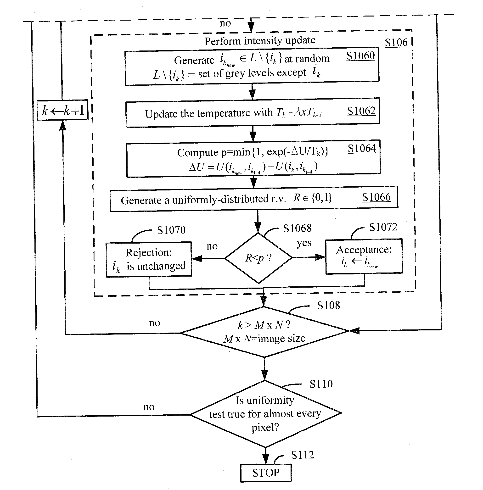
[0009]Accordingly, the present invention includes methods for the reduction of speckle noise reduction within an image and segmentation of an image. The speckle noise reduction method includes the steps of receiving an image comprising a plurality of pixels and establishing a coherence factor, a noise threshold factor, a pixel threshold factor, and a neighborhood system for pixels. The speckle noise reduction method can also include the steps of performing a uniformity test on a subset of pixels comprising a portion of the plurality of pixels, performing a noise detection test on the subset of pixels, and performing an intensity update on a pixel within the subset of pixels in response to the pixel being substantially non-uniform with respect to its neighborhood. The speckle noise reduction method can further include the step of repeating some or all of the foregoing steps for substantially all of the plurality of pixels in order to produce a speckle-noise reduced image.
[0010]The present invention further includes a method of segmenting an image. The segmentation method includes the steps of receiving an image comprising a plurality of pixels and establishing a coherence parameter and a number of classes. For each of the plurality of pixels, the segmentation method includes steps for comparing an intensity of each pixel to an intensity of one or more neighboring pixels, classifying each pixel into a class in response to a maximum value of a conditional probability function in response to the intensity of each pixel, and providing a segmented image in response to the classification of each of the plurality of pixels.
[0011]The methods of the present invention are based on the physical statistical properties of one or more pixels in an image. The methods of the present invention are practicable in a number of environments, including for example image processing systems for both SAR systems, ultrasound systems, and other coherent imaging systems. Each of the methods is practicable in real time or near real time, making them quite an efficient use of both time and computing power. Further details and advantages of the present invention are described in detail below with reference to the following Figures.

Problems solved by technology

Unfortunately, the efficiency of aerial data collection and visualization with SAR systems is often impeded by their high susceptibility to speckle noise.
The amplitudes of these signals interfere coherently at the antenna, which ultimately gives rise to the signal-dependent and grainy speckle noise formed in the SAR imagery.
Similarly, speckle noise in ultrasonic imaging is caused by the interference of energy from randomly distributed scatters, too small to be resolved by the imaging system.
Speckle noise degrades both the spatial and contrast resolution in ultrasonic imaging and thereby reduces the diagnostic value of the images.
Unfortunately, each of these approaches assumes that speckle noise is multiplicative relative to the image intensity.
While this assumption can be useful in simplifying the complex nature of speckle noise, it does not allow any of the foregoing techniques to substantially eradicate speckle noise from an image.
As in the case of speckle noise, each of these techniques is fundamentally flawed in that they either require affirmative user input to segment the image and / or they are adversely affected by the speckle noise otherwise inherent in SAR images.

Method used


Image

  • System and method for reduction of speckle noise in an image
  • System and method for reduction of speckle noise in an image
  • System and method for reduction of speckle noise in an image

Examples


Embodiment Construction

[0020]The following description of the preferred embodiments is provided to enable any person skilled in the art to make or use the present invention. Various modifications to these embodiments will be readily apparent to those skilled in the art, and the generic principles defined herein may be applied to other embodiments without departing from the spirit or scope of the invention as set forth in the appended claims.

[0021]The present invention includes a method of removing speckle noise from an image as well as a method of segmenting an image. Each of the methods of the present invention can be performed by automated systems, including for example image processing systems and the like. The methods of the present invention can be embodied in hardware, software, firmware or any other suitable means for causing an appropriate system to perform the requisite steps and provide a speckle noiseless and / or segmented image. The methods of the present invention are particularly well-suited ...


PUM


Abstract

The present invention includes methods for the reduction of speckle noise in an image and methods for segmenting an image. Each of the methods disclosed herein includes steps for analyzing the uniformity of a pixel within a plurality of pixels forming a portion of the image and, based on the uniformity of the intensity of the plurality of pixels, adjusting and / or replacing the pixel in order to produce a speckle-noise reduced image, a segmented image, or a segmented and speckle-noise reduced image. The methods of the present invention can employ for example conditional probability density functions, nonlinear estimator functions, convex energy functions and simulated annealing algorithms in the performance of their respective steps.

Description

CLAIM OF PRIORITY UNDER 35 U.S.C. §119[0001]The present application for patent claims priority to provisional application Ser. No. 60 / 834,508, entitled “Speckle Noise Reduction Based on Markov Random Field Model”, filed on Jul. 31, 2006, and assigned to the assignee hereof and hereby expressly incorporated by reference herein.BACKGROUND[0002]1. Field of the Present Invention[0003]The present invention relates generally to the field of image processing, and more specifically to the field of de-noising and segmenting coherent images.[0004]2. History of the Related Art[0005]Coherent imaging has a number of practical uses, for example in synthetic aperture radar (SAR) and ultrasonic imaging. For example, SAR has a number of advantages over other passive imaging systems because, as the SAR system emits its own radiation, it is not dependent upon any external source of radiation. Moreover, due to the long wavelengths, most SAR systems are capable of imaging the Earth's surface independent...

Claims


Application Information

Patent Timeline
Patent Type & Authority Applications(United States)
IPC IPC(8): G06K9/36G06V10/30G06V20/13
CPCG06K9/0063G06K9/40G06T2207/20012G06T5/002G06T2207/10132G06K9/4638G06V20/13G06V10/30G06V10/457G06T5/70
Inventor LANKOANDE, OUSSEINIHAYAT, MAJEEDSANTHANAM, BALU
Owner STC UNM
Learn More