
Image-pickup apparatus and focus control method

a technology of image-picking apparatus and focus control method, which is applied in the direction of camera focusing arrangement, printers, instruments, etc., can solve the problems of unstable captured image, insufficient responsive high-speed focus control, etc., and achieve high focusing accuracy, good responsiveness, and high speed

Active Publication Date: 2008-01-31
CANON KK
View PDF5 Cites 11 Cited by
  • Summary
  • Abstract
  • Description
  • Claims
  • Application Information

AI Technical Summary

Benefits of technology

The present invention provides an image-pickup apparatus and a focus control method that can quickly and accurately focus on a target without causing discontinuous movements of the focus lens. The apparatus includes a first detector that generates information based on the contrast of the captured image, a controller that repeatedly controls the focus lens using the first information, a second detector that outputs different information that is used to calculate the in-focus position and the driving amount of the focus lens, and a position detector that detects the position of the focus lens. The controller moves the focus lens towards the calculated in-focus position if the difference between the detected position and the calculated in-focus position is equal to or greater than a certain value, and repeats the control of the focus lens without using the second information if the difference is less than the certain value. This focus control method allows for quick and accurate focus with high responsiveness and accuracy.

Problems solved by technology

For this reason, the conventional hybrid AF method does not make full use of the features of the phase difference detection method, so that responsive high-speed focus control is not sufficiently realized.
This may make a captured image unstable.

Method used


Image

  • Image-pickup apparatus and focus control method
  • Image-pickup apparatus and focus control method
  • Image-pickup apparatus and focus control method

Examples


Embodiment Construction

[0023]A preferred embodiment of the present invention will now be described with reference to the accompanying drawings.

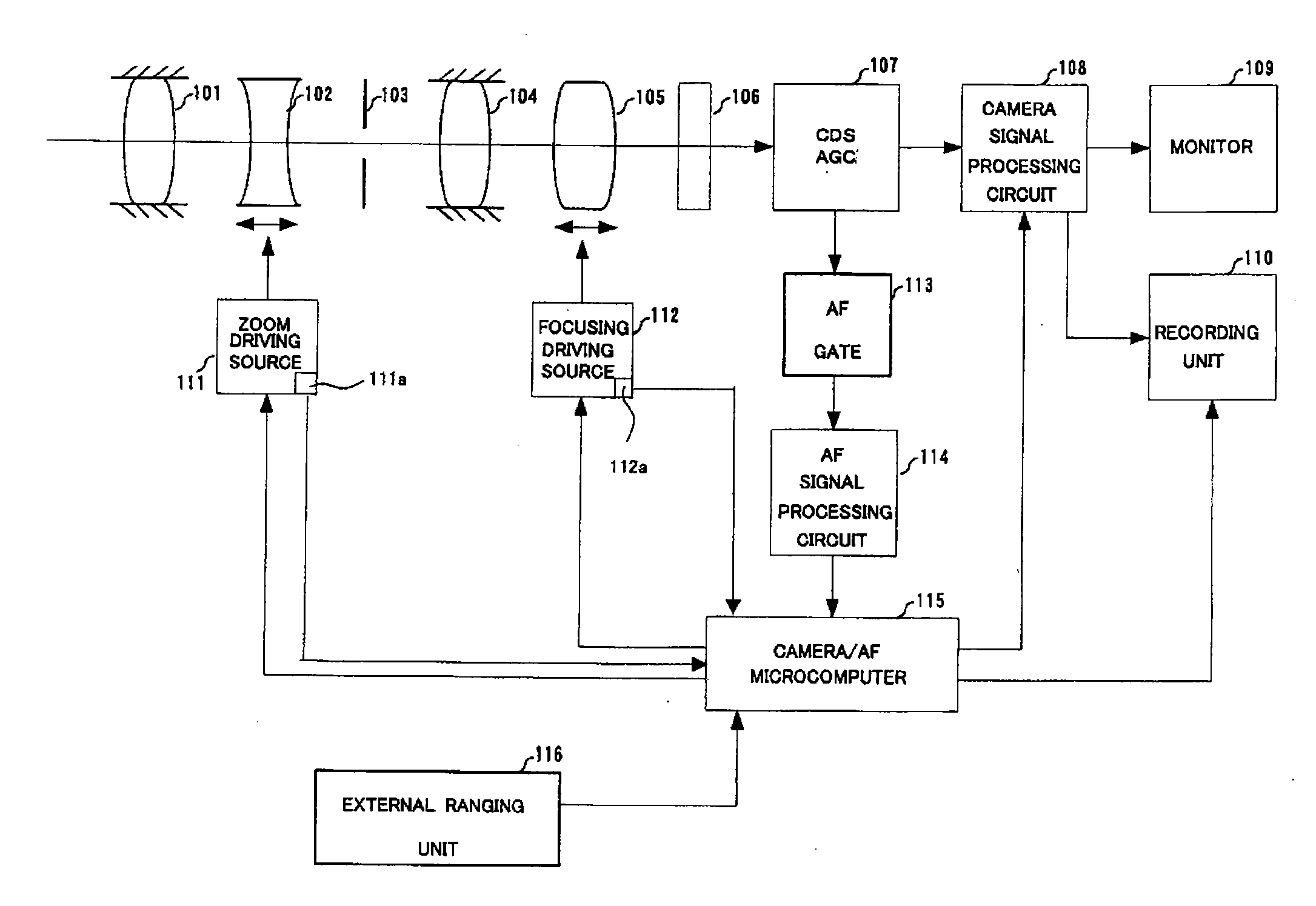
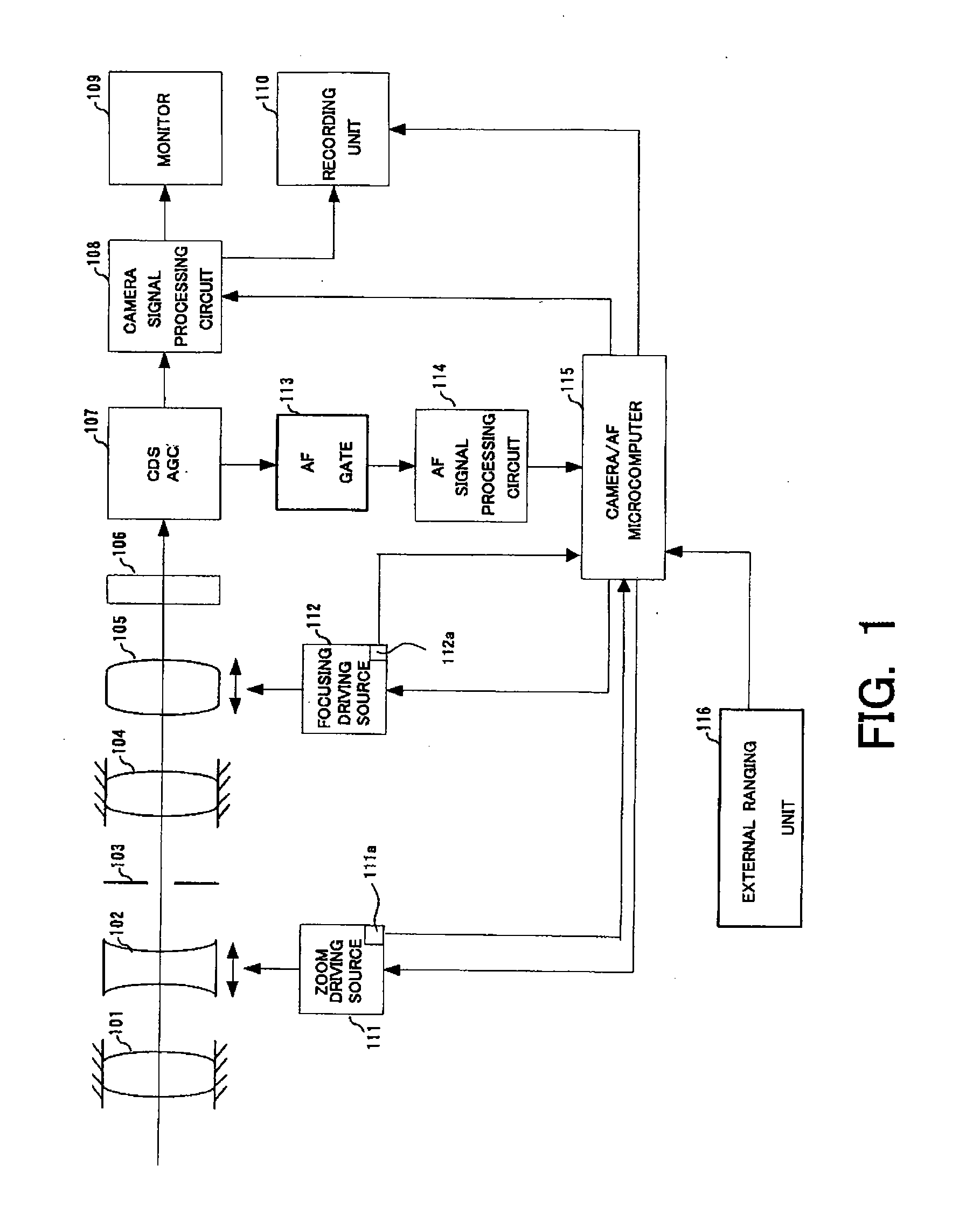
[0024]FIG. 1 shows the configuration of a video camera (image-pickup apparatus) that is an embodiment of the present invention. Note that although a description of a video camera will be given in this embodiment, alternative embodiments of the present invention include any other image-pickup apparatus such as a digital still camera.

[0025]In FIG. 1, reference numeral 101 denotes a first fixed lens, 102 denotes a magnification-varying lens which moves along an optical axis to vary the magnification, and 103 denotes a stop. Reference numeral 104 denotes a second fixed lens, and 105 denotes a focus / compensator lens (hereinafter referred to as a focus lens) which compensates for movement of the focal plane caused when the magnification is varied, and has a focusing function. The first fixed lens 101, magnification-varying lens 102, stop 103, second fixed lens 104, and f...


PUM


Abstract

An image-pickup apparatus includes a first detector generating first information corresponding to a contrast state, a focus lens controller, a second detector outputting second information used for calculating an in-focus position, and a focus lens position detector. If the difference between the detected focus lens position and the calculated in-focus position is equal to or greater than a first value, the controller moves the focus lens towards the calculated in-focus position, and if the difference is less than the first value, the controller repeats focus control using the first information without using the second information. The apparatus reduces discontinuous movements of the focus lens.

Description

BACKGROUND OF THE INVENTION[0001]The present invention relates to an image-pickup apparatus such as a video camera or a digital still camera and, more particularly, to a focus control method in the image-pickup apparatus.[0002]A mainstream method in auto-focus (AF) control of a video camera or the like is a TV-AF method which generates an AF evaluation value signal indicating the sharpness (contrast state) of image signals generated using an image-pickup element and searches for the position of the focus lens where the AF evaluation value signal is at the maximum.[0003]AF methods include an external ranging method (or an external phase difference detection method) in which an in-focus position of the focus lens is calculated from the distance to an object (object distance) detected by a ranging sensor provided independently of an image-pickup lens, and then the focus lens is moved to the in-focus position.[0004]In the external phase difference detection method, a light flux received...

Claims


Application Information

Patent Timeline
Patent Type & Authority Applications(United States)
IPC IPC(8): G03B13/32
CPCH04N5/23212G02B7/285H04N23/672H04N23/673
Inventor YASUDA, HITOSHI
Owner CANON KK
Learn More