Automatic transmission hydraulic line pressure regulator

a technology of hydraulic line pressure regulator and automatic transmission, which is applied in the direction of gearing control, gearing elements, gearing, etc., can solve the problems of reducing the performance of the vehicle, and setting the pressure higher than is necessary for the specific vehicle,

Inactive Publication Date: 2008-01-31
ATI PERFORMANCE PRODS
View PDF4 Cites 2 Cited by
  • Summary
  • Abstract
  • Description
  • Claims
  • Application Information

AI Technical Summary

Benefits of technology

[0027] It is a further object of the present invention to provide a line pressure regulating system for an automatic transmission that is precisely adjustable on a test rig without requiring disassembly of the valve body and / or replacement of components.

Problems solved by technology

While higher line pressures can be desirable to increase the holding power of the clutch packs, setting the pressure higher than is necessary for the specific vehicle wastes engine power that could otherwise be used to drive the vehicle forward.
Thus, pressures that are set too high for the particular vehicle can decrease the performance of the vehicle by shunting propelling engine power to create unnecessarily high line pressures.
Setting the line pressure any higher wastes engine power that could otherwise be propelling the vehicle.
There are several disadvantages to the standard approach to regulating the line pressure in a Powerglide® transmission.
First, the various components described above that can affect the line pressure cannot be readily removed and replaced in the valve body without removing either the transmission from the vehicle or the valve body from the transmission.
This is time consuming and increases the chances of contamination and leakage of the valve body caused by the assembly and reassembly.
This increases inventory costs for maintaining this supply of parts and also increases the complexity of determining the correct combination of parts to derive the desired line pressure.
Such complexity can easily push adjustment of the line pressure beyond the capability of the vehicle owner, and prevent the vehicle owner from himself being able to fine tune the line pressure to his particular vehicle to maximize the performance of the vehicle.
In fact, at the present time, adjustment of the line pressure in a Powerglide® transmission is not generally considered to be a vehicle owner task.
Further, it is known for the hydraulic portion of the resistive force to be problematic.
That is, the boost valve is known to become jammed in the boost sleeve, often through contamination between the boost valve and boost sleeve, thereby either completely eliminating the hydraulic portion of the resistive force if the boost valve jams in a position away from the line pressure valve so that it does not contact the line pressure valve under normal movement of the line pressure valve (thereby leaving the line pressure too low) or by jamming in a position that prevents full movement of the line pressure valve (and thereby causing the line pressure to become higher than desired).
This can seriously affect the performance, and even drivability, of the vehicle, and can also damage components of the transmission and vehicle.
Resolving this problem requires, at the least, disassembly of the valve body to remove the contamination, and may require replacement of the boost sleeve / boost valve pair if either component has been damaged.

Method used


Image

  • Automatic transmission hydraulic line pressure regulator
  • Automatic transmission hydraulic line pressure regulator
  • Automatic transmission hydraulic line pressure regulator

Examples


Embodiment Construction

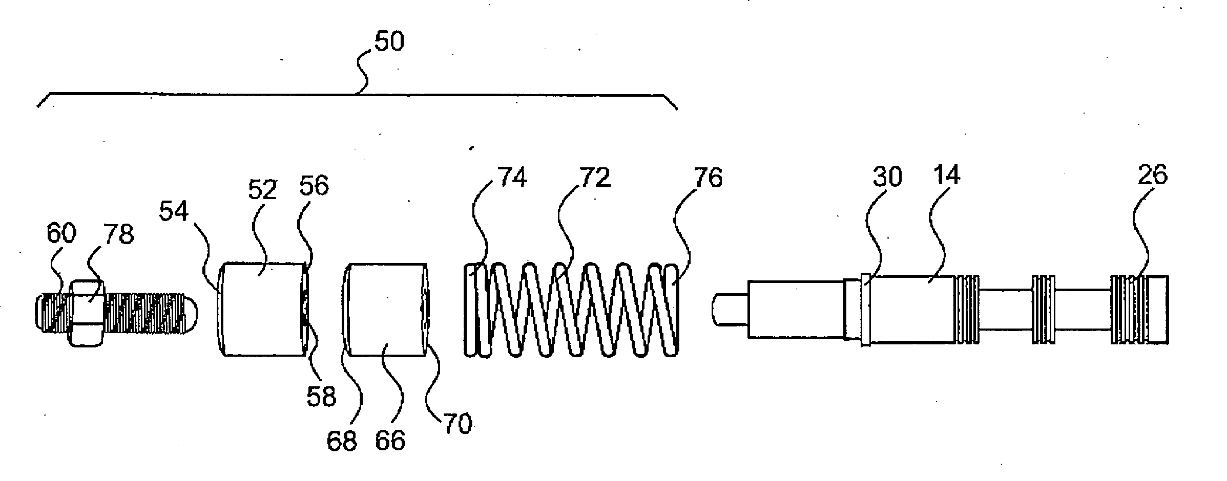
[0036] The line pressure regulating system 50 of the present invention includes a first body 52 of generally cylindrical shape having a first side 54, a second side 56 and a threaded bore 58 passing through the first body 52 from the first body first side 54 to the first body second side 56. A threaded adjuster 60 is threadingly engaged with the threaded bore 58 and can be threaded into and out of the threaded bore 58 to change the axial position of the threaded adjuster 60 with respect to the first body 52. The threaded adjuster 60 has a first end 62 exposed to an exterior of the valve body 12, allowing for rotation of the threaded adjuster 60 from the exterior of the valve body (see FIG. 6). The first end 62 of the threaded adjuster 60 can be provided with a hex configuration, hex socket configuration, slotted configuration, or other types of configurations for being engaged by a wrench, hex key, screwdriver, Torx® driver or other type of hand tool to assist in manually rotating t...


PUM


Abstract

An automatic transmission line pressure regulator includes a first body for installation in a valve bore distant from a line pressure valve and having a threaded bore passing therethrough, a threaded adjuster axially engaged in the threaded bore and rotationally adjustable with respect to the first body, a second body for installation in the valve bore and engagement with the threaded adjuster and a spring for installation between and engagement with the second body and the line pressure valve. Rotation of the threaded adjuster with respect to the first body alters an axial position of the adjuster, the second body and a first end of the spring, thereby altering a pre-load on the spring to alter a resistive force against movement of the line pressure valve caused by line pressure, and thusly, regulates line pressure.

Description

[0001] This application claims priority to U.S. Provisional Application No. 60 / 832,938, filed Jul. 25, 2006, which application is incorporated by reference herein.BACKGROUND [0002] The present invention relates to automatic transmissions, and more specifically, to an adjustable pressure regulator for adjusting a hydraulic pressure in a hydraulic circuit of an automatic transmission. [0003] In known automatic transmissions, such as the General Motors® Powerglide® automatic transmission, a hydraulic line pressure in the transmission is used to set the clamping force of clutch packs in the transmission. This line pressure can be changed to compensate for various factors relating to the vehicle configuration and use. In standard road use, such line pressures were set at the factory, generally were set in a range of 120-130 psi, and were never changed. Higher pressures provided more clamping force for the clutch packs and resulted in less likelihood of slippage through the clutch packs. ...

Claims


Application Information

Patent Timeline
Patent Type & Authority Applications(United States)
IPC IPC(8): G05D13/36
CPCG05D16/10F16H61/0009Y10T477/6939F16H61/0276F16H61/0021
Inventor BRUETTE, RANDOLPH H.
Owner ATI PERFORMANCE PRODS
Why Eureka
Try Eureka