Image Processor for Medical Treatment Support

a technology of image processing and medical treatment, applied in the field of image processing for medical treatment support, can solve the problems of increasing the dose of radiation exposure on the patient, the inability to depend on visual observation to determine the treatment area, and the difficulty in visually distinguishing the freezing region from the lesion border, so as to improve the remaining treatment planning and reduce the number of images

Active Publication Date: 2008-01-31
FUJIFILM HEALTHCARE CORP
View PDF3 Cites 36 Cited by
  • Summary
  • Abstract
  • Description
  • Claims
  • Application Information

AI Technical Summary

Benefits of technology

[0046]According to the present invention, by estimating the time needed for completing the treatment upon monitoring it, it is possible to improve remaining treatment planning and to reduce the number of images that must be obtained. Also, the lesion and the region of the temperature effective for the treatment can be easily calculated.

Problems solved by technology

However, there are problems related to monitoring these complicated procedures as images need to be acquired sequentially during treatment, additionally in the case of using X-ray CT apparatus, that the dose of radiation exposure on the patient increases with the number of images acquired.
Also, even though the region being treated needs to be somewhat larger than the lesion, there is a demand to reserve the normal tissues as much as possible, thus the need to depend on visual observation for determining the region for treatment is unavoidable at this point.
However, it has been difficult to visually distinguish a freezing region from the lesion border as the treatment.
Further, even though there is basic data in what degree of temperature is pathologically necessary for necrotization of tissues, it has been difficult to carry out reliable treatment procedure since there was no means to measure it quantitatively and check the relationship between the lesion and the temperature distribution.

Method used


Image

  • Image Processor for Medical Treatment Support
  • Image Processor for Medical Treatment Support
  • Image Processor for Medical Treatment Support

Examples


embodiment 1

[0058]Hereinafter embodiment 1 of the present invention will be described referring to the attached drawings.

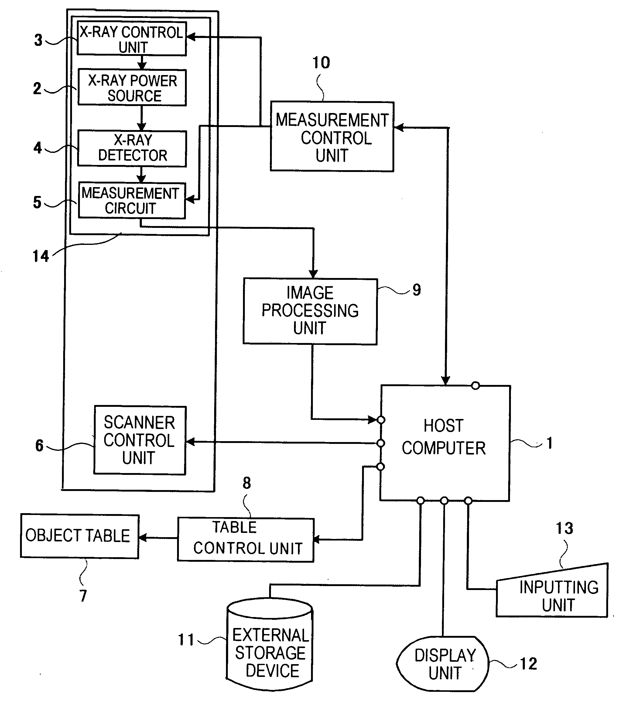
[0059]FIG. 1 is a block diagram showing an embodiment of an image processor for medical treatment support by the present invention. This image processor for medical treatment support comprises:[0060]host computer 1 for overall controlling of the entire system;[0061]turntable 14 being mounted with the measurement units such as X-ray power source 2, X-ray controlling unit 3, X-ray detector 4 and measurement circuit 5;[0062]scanner controlling unit 6 for controlling the rotating scan of turntable 14;[0063]transportable object table 7 and table controlling unit 8 for determining the position of an object to be examined or for the helical scanning; and[0064]image processor 9 for executing various types of image processing such as pre-processing or reconstructive processing. Measurement controlling unit 10 is for controlling the operation of X-ray controlling unit 3 and measurement...

second embodiment

The Second Embodiment

[0086]The configuration or the process of the present embodiment is basically the same as embodiment 1, unless particularly mentioned otherwise. Also, the same reference number illustrates the same portion as in embodiment 1.

[0087]FIG. 8 is a diagram showing the configuration of an image processor relating to another embodiment of the image processor for medical treatment support in the present invention. This image processing unit 9 comprises measurement calculation unit 82, measurement / temperature converting unit 83, color table 84, inputting switch 85, look-up table (LUT) 86, image synthesizing unit 87, and image memory 81 as shown in FIG. 8. Image memory 81 is for storing temporarily the measurement data and measurement value being outputted from measurement circuit 5 or the tomographic image being obtained by reconstructing them. Look-up table (LUT) 86 is consistently storing a look-up table for giving a gray scale for the purpose of displaying CT images, a...

embodiment 3

[0096]The above-mentioned embodiment 1 was about estimating and displaying the time up to the completion of the treatment. Instead of or additional to the time display, the images of treatment progress may be created and displayed. By this function, for example, the time or condition being required for the ice ball to cover the lesion portion sufficiently can be identified sequentially and instantly.

[0097]Embodiment 3 will now be described referring to FIG. 10 and FIG. 11. The configuration or the process of the present embodiment is basically the same as embodiment 1 unless mentioned otherwise. Also, the same reference number illustrates the same portion as in embodiment 1.

[0098]The above-mentioned display of the treatment progress image can be implemented, for example, by effecting a change on the function of total treatment-time estimating unit 94 being described in embodiment 1 to estimate the degree of progress by the minute, and by superimposing those images of completing the ...


PUM


Abstract

A scope of medical treatment as an object of medical treatment is predetermined, and an image for treatment region considered as already completed treatment in the course of medical treatment is acquired.
Time up to completion of the whole scope of intended treatment regions is estimated on the basis of the already completed treatment region.
Further, any changes of sites under treatment are displayed by color indication.
Still further, the time up to completion of medical treatment is determined in a way easy to understand by simulating an image of treatment completion with respect to multiple treatment periods.
By virtue of these characteristics, not only can an improvement of medical treatment accuracy be attained but also the total time and exposure for medical treatment can be minimized.

Description

BACKGROUND ART[0001]The present invention relates to an image processor for medical treatment support by which improvement in planning and efficacy can be achieved by monitoring an image of a target area upon treatment of the target area of an object to be examined.TECHNICAL FIELD[0002]The apparatuses such as X-ray CT or MRI are commonly known to be useful for image diagnosis, and are also widely applied as a guide for monitoring treatment of surgical operations or biopsy, not only as a mere diagnostic device for displaying images. The objective of using these apparatuses in the case of a biopsy is to figure out the positional relations between a puncture needle and a lesion, and the means in use are such as CT / MR fluoroscopy that enables grasping the positional relations in real time by contriving the reconstruction process and sequentially renewing the image. As for treatment, availability of various means and methods such as hyperthermia using a laser, RF (Radio Frequency) or cry...

Claims


Application Information

Patent Timeline
Patent Type & Authority Applications(United States)
IPC IPC(8): A61B6/03G06T7/00
CPCG06T7/0012G06F19/321G16H30/40
Inventor MIYAZAKI, OSAMUHAYASHI, HIROMITSU
Owner FUJIFILM HEALTHCARE CORP
Why Eureka
Try Eureka