
Cable Made Of High Strength Fiber Composite Material

Active Publication Date: 2008-02-07
TOKYO ROPE MFG
View PDF8 Cites 34 Cited by
  • Summary
  • Abstract
  • Description
  • Claims
  • Application Information

AI Technical Summary

Benefits of technology

[0013] According to the invention, the following excellent advantages are obtained.
[0014] 1) Since the twist angle is 2 to 12 degrees, high tensile strength is kept, and since nonuniformity hardly appears in length of respective strands, tension is evenly applied to respective strands or respective element wires, consequently designed strength can be securely realized.
[0015] 2) Since a cable is formed by using a cable, which is formed by singly twisting a plurality of high strength fiber composite materials including a wire of high-strength low-elasticity fiber impregnated with thermosetting synthetic resin, as a strand, and twisting the strands together, axial tension applied to each strand is even, even if the cable is bent, in addition, since the cable is in a structure having a stable shape, when the cable is wound on a reel or unwound from the reel, the shape deformation hardly occurs, consequently it can be wound in a lapped manner. 3) Furthermore, when the cable is inserted into a cylinder or hole, it is hardly damaged by buckling. 4) Since the cable has large surface area of the periphery, when end anchoring is performed, sufficient anchoring force can be obtained without need of breaking ends unlike the case of the multilayer twist cable. 5) Since a twist direction of the cable is opposite to a twist direction of the strands, rotation is small, and distortion or shape deformation hardly occurs. 6) The strands can be easily twisted together by an existing twisting machine, and intended tension can be obtained only by changing the number of strands (single twist cables) to be twisted together.

Problems solved by technology

However, there have been the following drawbacks in such a usual cable made of the high strength fiber composite material.
Therefore, when an end anchoring portion is provided for connecting the cable to another object or adding tension, sufficient anchoring efficiency is hardly obtained even if resin or cement is poured into a sleeve and solidified in order to unify the sleeve and the cable, and complicated operation of breaking a cable end into respective element wires is necessary to obtain sufficient adhesion.
Moreover, since the multilayer twist structure cable is in a configuration where all element wires are twisted together in an S or Z direction, equipment for twisting becomes larger with increase in number of element wires, leading to significant increase in equipment cost and operation cost.
In the latter parallel bundle structure cable, when respective unit cables are not uniform in length, or when the cable is disposed with being bent by a deflection portion or the like, tension is not evenly transmitted to each of unit cables in introducing tension into the cable, consequently originally designed tension of the cable may not be achieved.
Moreover, when the cable is wound on a reel to carry the cable, shape deformation occurs, therefore handling is difficult, in addition, bending stress acts due to difference in diameter between the inside and the outside of the cable, consequently the cable may be damaged.
Furthermore, since the cable is simply formed by evenly drawing the unit cables in parallel, it is weak against torsion, and in particular, when it is distorted in a direction opposite to a twist direction of the unit cables, element wires configuring the unit cables are spaced from one another, leading to damage of the cable.
In addition, the cable is fatally weak against compression (buckling) in an axial direction.
Moreover, in the case that a cylindrical body is attached on the periphery of the cable, and resin or cement is filled into the cylindrical body so that the cable and the cylindrical body are unified to obtain an anchoring portion, or the case that a sheath tube storing the cable is filled with a specific gravity regulator to use the cable as a ground anchor, filler inevitably flows out to the outside through gaps between element wires of the unit cables or gaps between the unit cables, therefore complicated treatment is necessary to fill the gaps.

Method used


Image

  • Cable Made Of High Strength Fiber Composite Material
  • Cable Made Of High Strength Fiber Composite Material
  • Cable Made Of High Strength Fiber Composite Material

Examples


example 1

[0049] Hereinafter, examples of the invention will be described with reference to drawings.

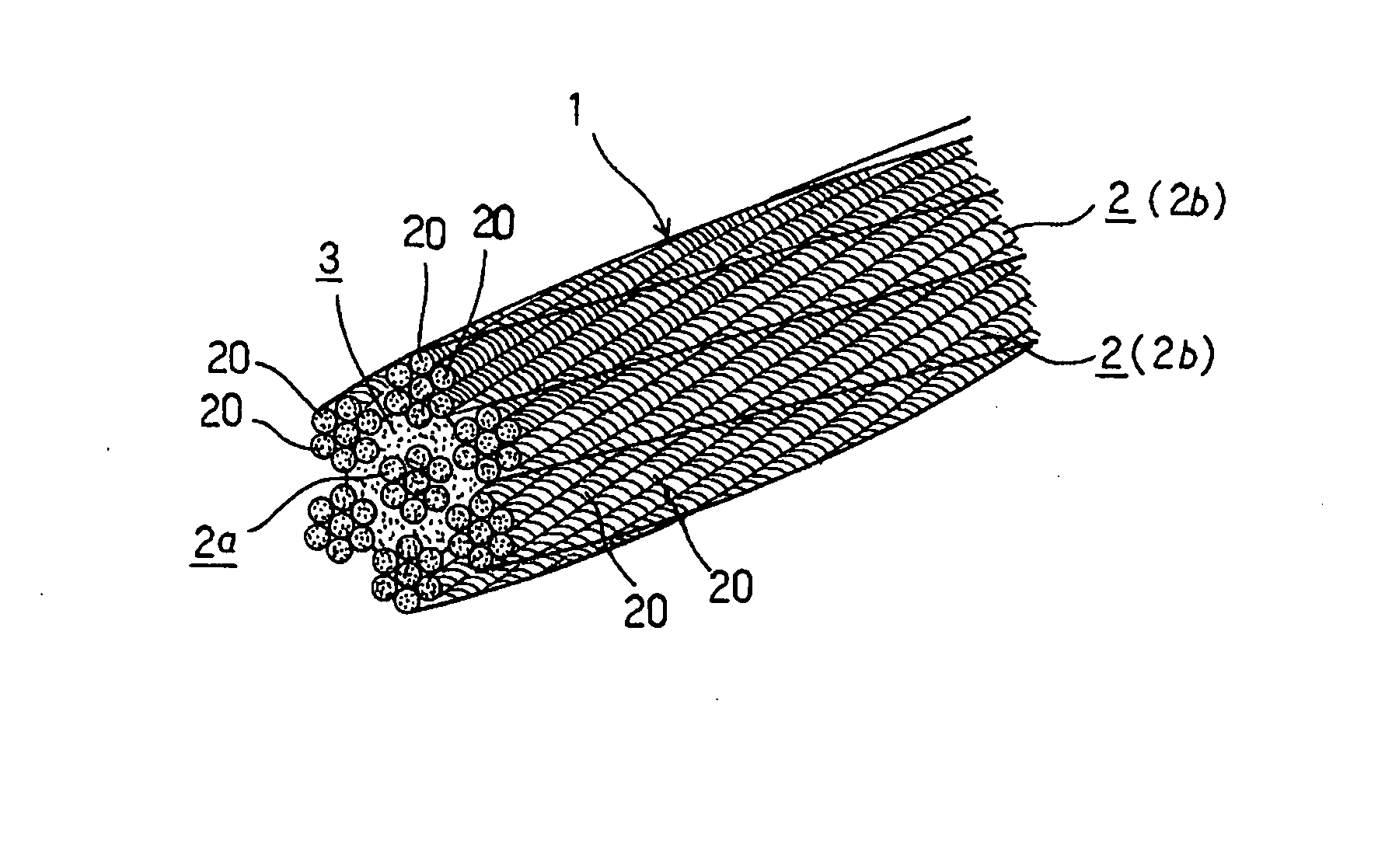
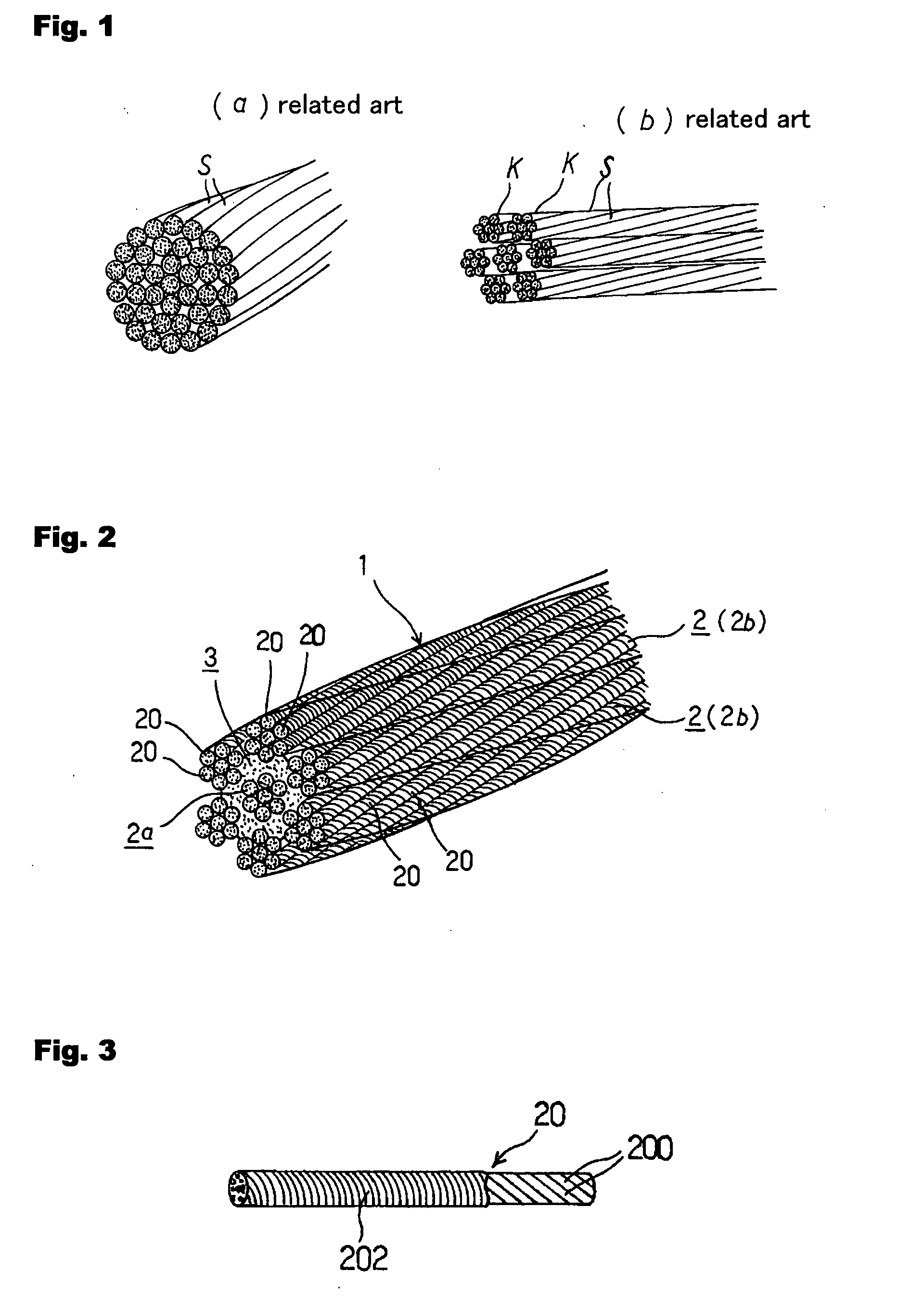
[0050]FIG. 2 shows an embodiment of a cable according to the invention, wherein a reference 1 indicates a cable as a whole made of a high strength fiber composite material, and a reference 2 indicates a strand including cables having a structure where a plurality of element wires 20 including high-strength low-elasticity fiber compounded with thermosetting resin are evenly drawn and twisted in an S or Z direction (this is called single twist).

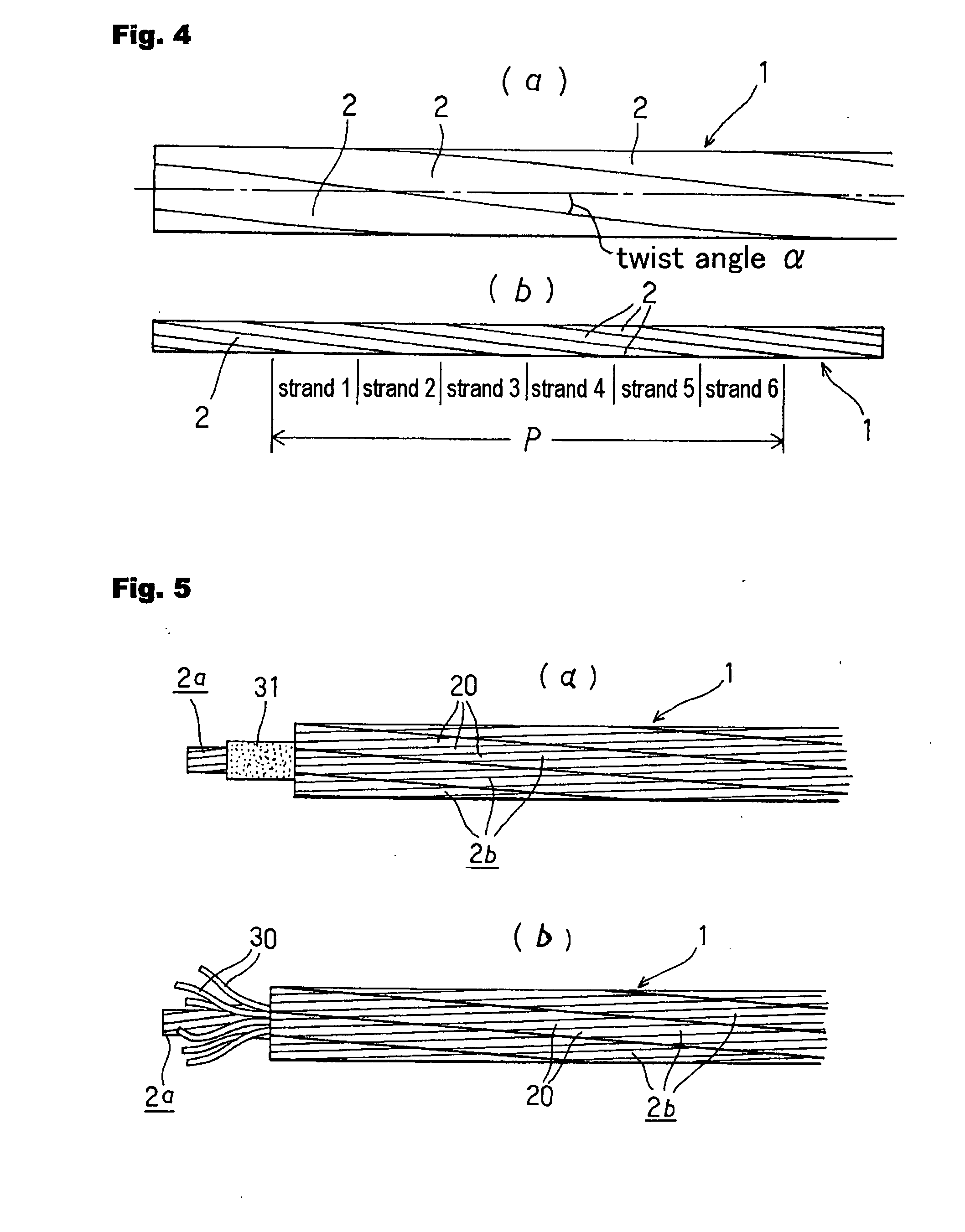
[0051] The cable 1 is formed in a way that a plurality of the strands (seven strands in the figure) having the single twist structure are evenly drawn, and twisted together at a long twist pitch, that is, at an angle of 2 to 12 degrees as a twist angle α as shown in FIG. 4 into a cable having a predetermined thickness.

[0052] In this example, a single strand 2a is disposed in the center as the core strand, around which six strands 2b are disposed as sid...


PUM

PropertyMeasurementUnit
Angleaaaaaaaaaa
Angleaaaaaaaaaa
Strengthaaaaaaaaaa

Abstract

A practical cable made of a high strength fiber composite material is provided, which has high and stable strength, in addition, has even axial tension against bending and thus has a stable shape, and can be wound on a reel without shape deformation, and is hardly buckled when it is inserted into a hole or cylinder. [Means for Resolution] A cable formed by singly twisting a plurality of high strength fiber composite materials is used as a strand, and a plurality of the strands are twisted together at a twist angle of 2 to 12 degrees in a direction opposite to a twist direction of the strands, so that a double twist structure is made.

Description

TECHNICAL FIELD [0001] The present invention relates to a cable, and particularly relates to a cable made of a high strength fiber composite material. BACKGROUND ART [0002] A cable using a composite material of high strength fiber and thermosetting resin as a material has properties such as high strength, low elasticity, lightweight, high corrosion resistance, high fatigue resistance, and non-magnetic property. Therefore, it is increasingly applied to various fields as a material to replace a usual steel rope or strand cable, and a PC tendon member. [0003] There are various kinds in such a cable made of the high strength fiber composite material, and in reinforcing means of a large structure requiring high tension such as a cable for preventing deformation of a large roof, a tension tendon member of a main girder of a bridge, an outer cable of a main girder of a bridge, a stay cable of a cable stayed bridge, a main cable of a suspension bridge, or a ground anchor, a “multilayer twis...

Claims


Application Information

Patent Timeline
IPC IPC(8): D07B1/16
CPCD07B1/025D07B1/165D07B2205/205D07B2205/2096D07B2205/3007D07B2501/203D07B2801/10
Inventor USHIJIMA, KENICHI
Owner TOKYO ROPE MFG
Learn More