

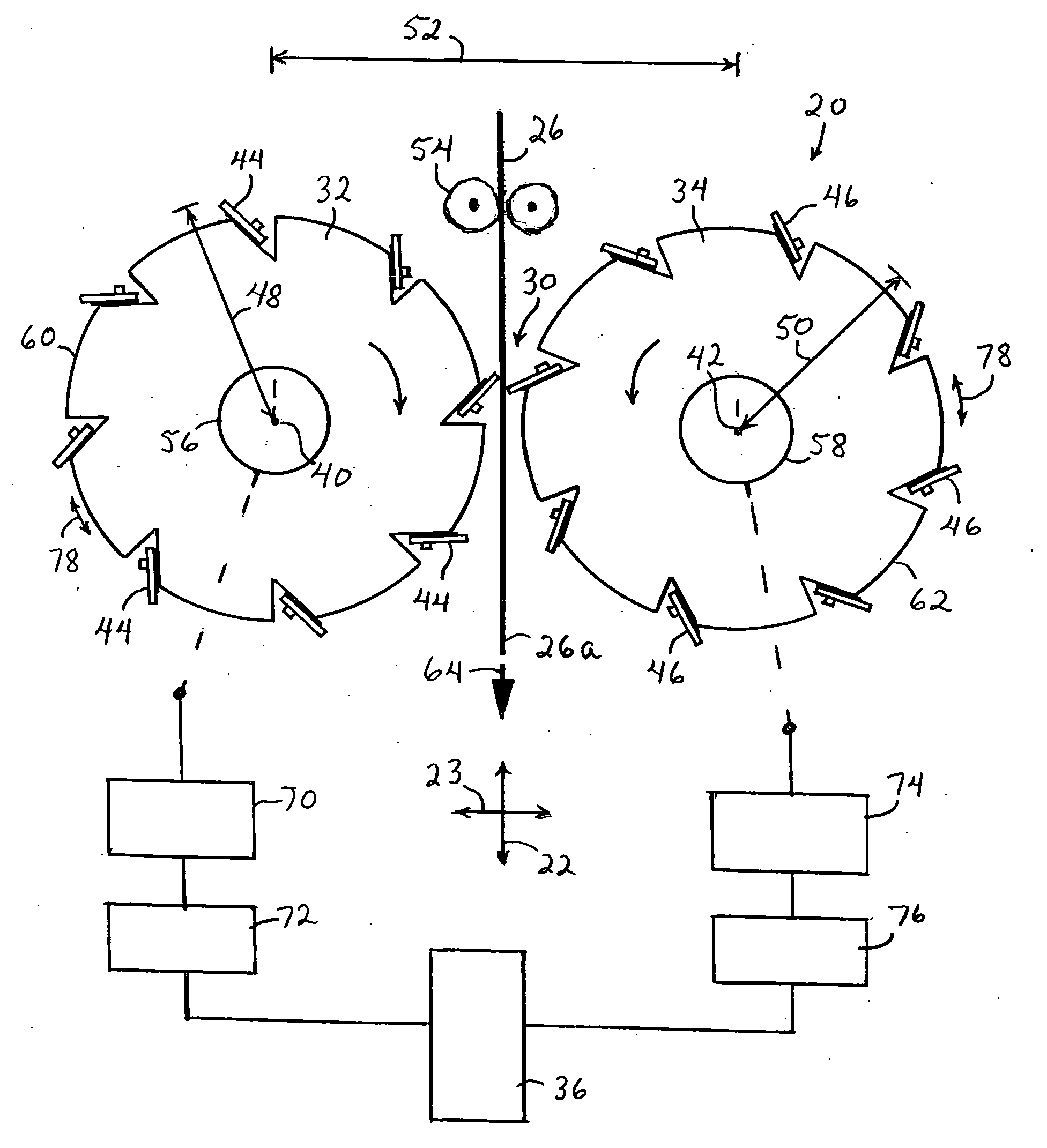
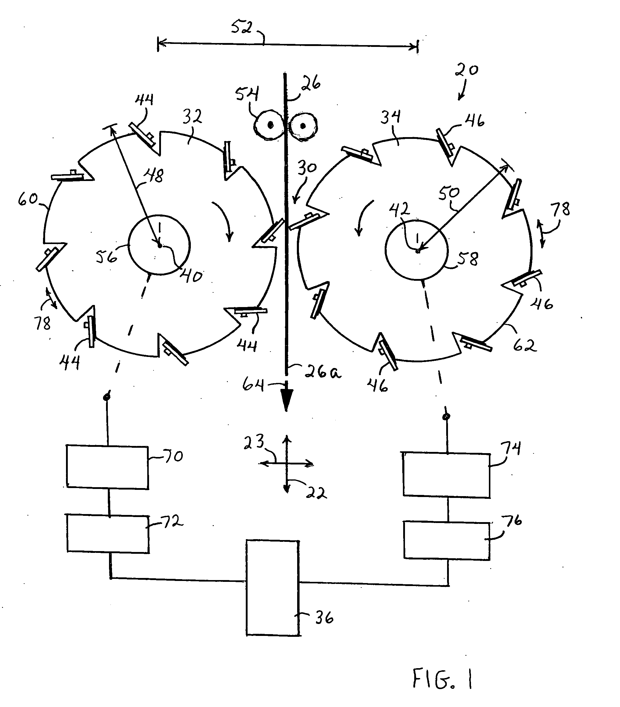
Dual roll, variable sheet-length, perforation system
a perforation system and variable sheet length technology, applied in the field of selective perforation of moving target webs, can solve the problems of high rate of wear, requiring frequent changing of knife and anvil blades, and lack of perforations in webs
- Summary
- Abstract
- Description
- Claims
- Application Information
AI Technical Summary
Benefits of technology
Problems solved by technology
Method used
Image

Examples
Embodiment Construction
[0017]It should be noted that, when employed in the present disclosure, the terms “comprises”, “comprising” and other derivatives from the root term “comprise” are intended to be open-ended terms that specify the presence of any stated features, elements, integers, steps, or components, and are not intended to preclude the presence or addition of one or more other features, elements, integers, steps, components, or groups thereof.
[0018]By the terms “particle,”“particles,”“particulate,”“particulates” and the like, it is meant that the material is generally in the form of discrete units. The units can comprise granules, powders, spheres, pulverized materials or the like, as well as combinations thereof. The particles can have any desired shape such as, for example, cubic, rod-like, polyhedral, spherical or semi-spherical, rounded or semi-rounded, angular, irregular, etc. Shapes having a large greatest dimension / smallest dimension ratio, like needles, flakes and fibers, are also contem...
PUM
| Property | Measurement | Unit |
|---|---|---|
| web pitch distance | aaaaa | aaaaa |
| web speed | aaaaa | aaaaa |
| web speed | aaaaa | aaaaa |
Abstract
Description
Claims
Application Information