Plug and method for fixing at least two devices

a technology of plug and fixing device, which is applied in the direction of expansible closure, light support device, candle holder, etc., can solve the problems that the plug may also be undone, and achieve the effects of improving the play between the through-hole and the non-compressible elements of the plug, improving the installationability, and facilitating the sliding of the tension elemen

Inactive Publication Date: 2008-02-07
AIRBUS OPERATIONS GMBH
View PDF5 Cites 18 Cited by
  • Summary
  • Abstract
  • Description
  • Claims
  • Application Information

AI Technical Summary

Benefits of technology

[0008] In the case of the object of the embodiment, too, its use may be associated with a certain sealing effect, which is altogether desirable. The compression element may be at least partly or entirely outside the through-opening of the components. If the compression element is compressed, it may establish contact with an edge region of an opening cross section of the through-opening that is nearest to it. The static friction provided by the contact may has an advantageous effect in that, as a result of a change in shape of the compression element, any forces that act laterally on the devices are dampened.
[0009] Furthermore, in its compressed state, the compression element may have a certain centering effect on the position of the plug within the through-holes. As a result of the centering effect, for example, the play between the through-holes and the non-compressible elements of the plug may be increased. This not only results in improved installability, but it also prevents in a particular elegant manner, any direct effect of lateral forces acting on non-compressible elements of the plug, in particular of the tension element.
[0010] Improved guidance is achieved in that the plug comprises a guide sleeve that may be pushed onto the tension element such that it establishes area-shaped contact with the compression element. Furthermore, the guide sleeve results in easier sliding of the tension element. The outside diameter of the guide sleeve depends on the through-openings.
[0011] In this arrangement, the use o

Problems solved by technology

However, the plug may also be

Method used


Image

  • Plug and method for fixing at least two devices
  • Plug and method for fixing at least two devices
  • Plug and method for fixing at least two devices

Examples


Embodiment Construction

[0020] The examples described and drawings rendered are illustrative and are not to be read as limiting the scope of the invention as it is defined by the appended claims.

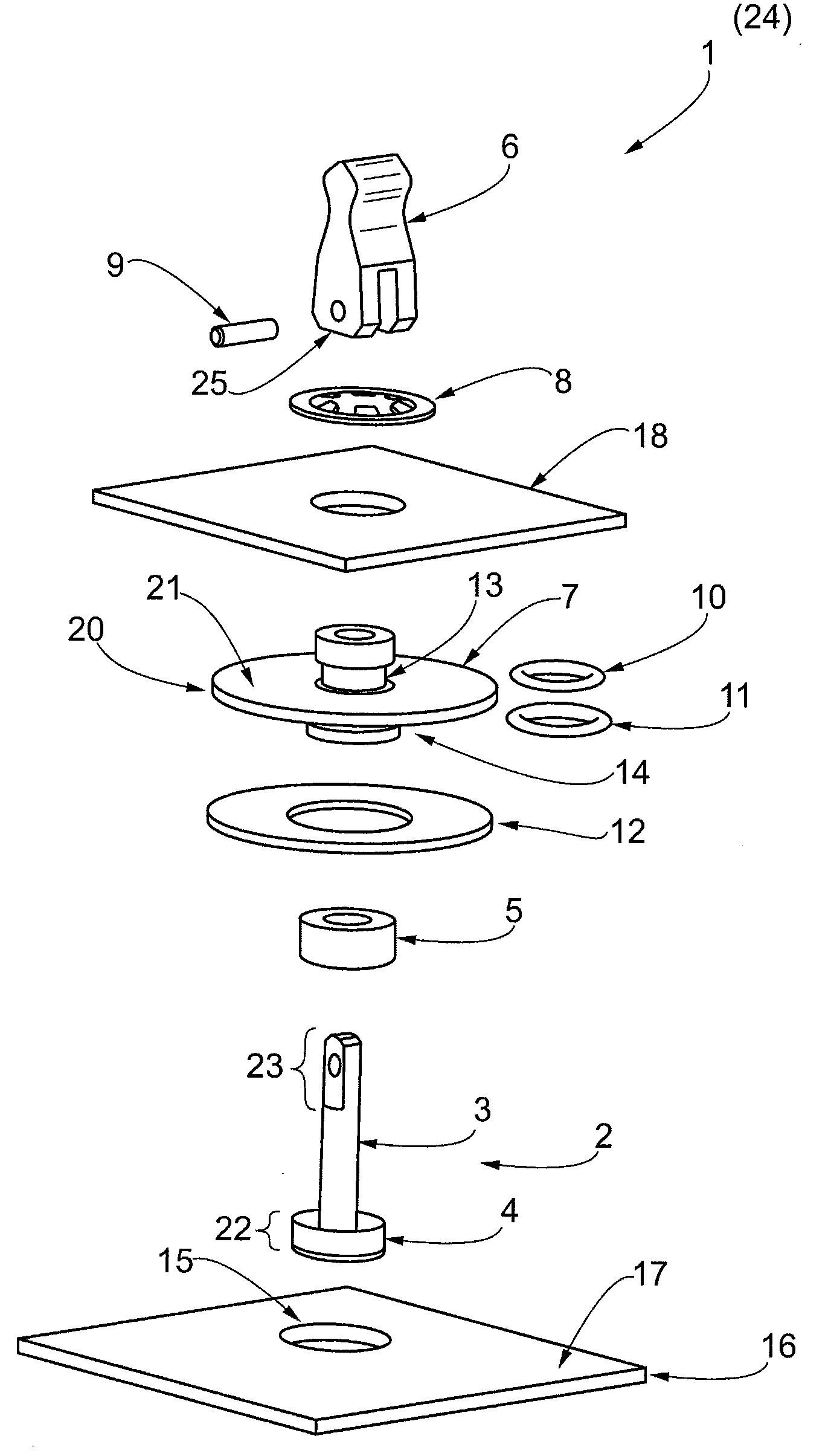
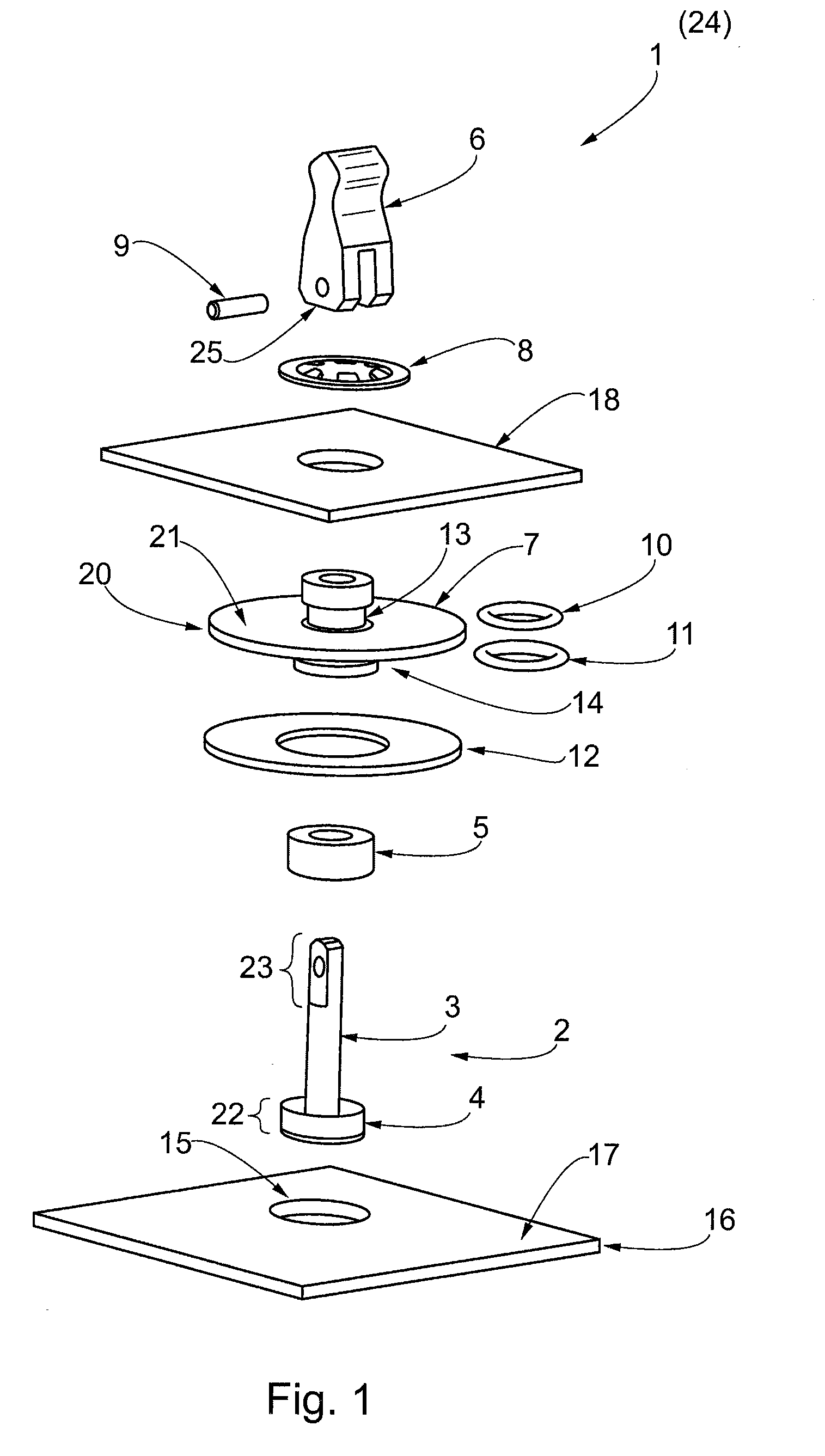
[0021] A plug 1 such as illustrated in FIG. 1, may comprise a tension element 2, such as the one shown in FIG. 1, which is made of a thermoplastic material. The tension element 2 comprises a coupling member 23 on one end of a tension rod 3 and a tension stamp 4 on the opposite end of tension rod 3. As an alternative, the tension element may be made of a metal, for example. The plug 1 includes a compression element 5, which may be made of silicon. When assembling the plug 1, the compression element 5 may slide onto the tension rod 3 of the tension element 2 and may contact the tension stamp 4. Furthermore, the plug 1 comprises a lever element 6; a guide sleeve 7; and a limit stop element, such as a captive lock washer 8, that may be snapped into a groove 13 of the guide sleeve 7; and a pin 9 used for coupling the l...


PUM


Abstract

A plug and a method for fixing at least two devices, includes a tension element, a pin, a lever element and a compression element. In one example, the tension element includes a tension stamp on a first end and a coupling member on a second end and a lever element includes a first sliding and a coupling element, with the pin coupling the lever element with the tension element. A compression element having an area-shaped contact that is capable of sliding onto the tension element until the area-shaped contact contacts the tension stamp. When the lever element is coupled to the tension element by a pin and is engaged by using a lever movement, a compression element is compressed by shortening a distance between the tension stamp and the lever element.

Description

REFERENCE TO RELATED APPLICATION [0001] This application claims the benefit of the filing date of German Patent Application No. 10 2006 036 083.4 filed. Aug. 2, 2006 and of U.S. Provisional Patent Application No. 60 / 821,149 filed Aug. 2, 2006, the disclosures of which applications are hereby incorporated herein by reference.FIELD OF THE INVENTION [0002] The field relates to a plug and a related method suitable for fixing at least two devices, in particular for fixing devices of an aircraft. The devices to be fixed may be panels, wherein a first panel is, for example, connected to the aircraft body, while a second panel forms, for example, part of a housing for electronic devices. BACKGROUND OF THE INVENTION [0003] In order to fix such devices together, a known plug made by Hartwell Corp., U.S.A., comprises a socket and a plunger that may be inserted into the socket. In this arrangement, the socket is inserted, with a degree of initial tension, into a first through-opening in the for...

Claims


Application Information

Patent Timeline
IPC IPC(8): F16B21/02
CPCF16B2/185Y10T403/591Y10T24/44026Y10T403/75
Inventor SCHMITZ, GUENTER
Owner AIRBUS OPERATIONS GMBH
Why Eureka
Try Eureka