Method and apparatus for imaging with imaging detectors having small fields of view

Active Publication Date: 2008-02-07
GE HEALTHCARE ISRAEL
View PDF26 Cites 102 Cited by
  • Summary
  • Abstract
  • Description
  • Claims
  • Application Information

AI Technical Summary

Problems solved by technology

In nuclear medicine (NM) imaging, the time required to acquire a scan of a patient can be long, leading to patient discomfort.
Furthermore, if the patient moves, the image may be degraded and the scan may need to be repeated.
In addition to the cost of the equipment, a high cost of operation may also be realiz

Method used


Image

  • Method and apparatus for imaging with imaging detectors having small fields of view
  • Method and apparatus for imaging with imaging detectors having small fields of view
  • Method and apparatus for imaging with imaging detectors having small fields of view

Examples


Embodiment Construction

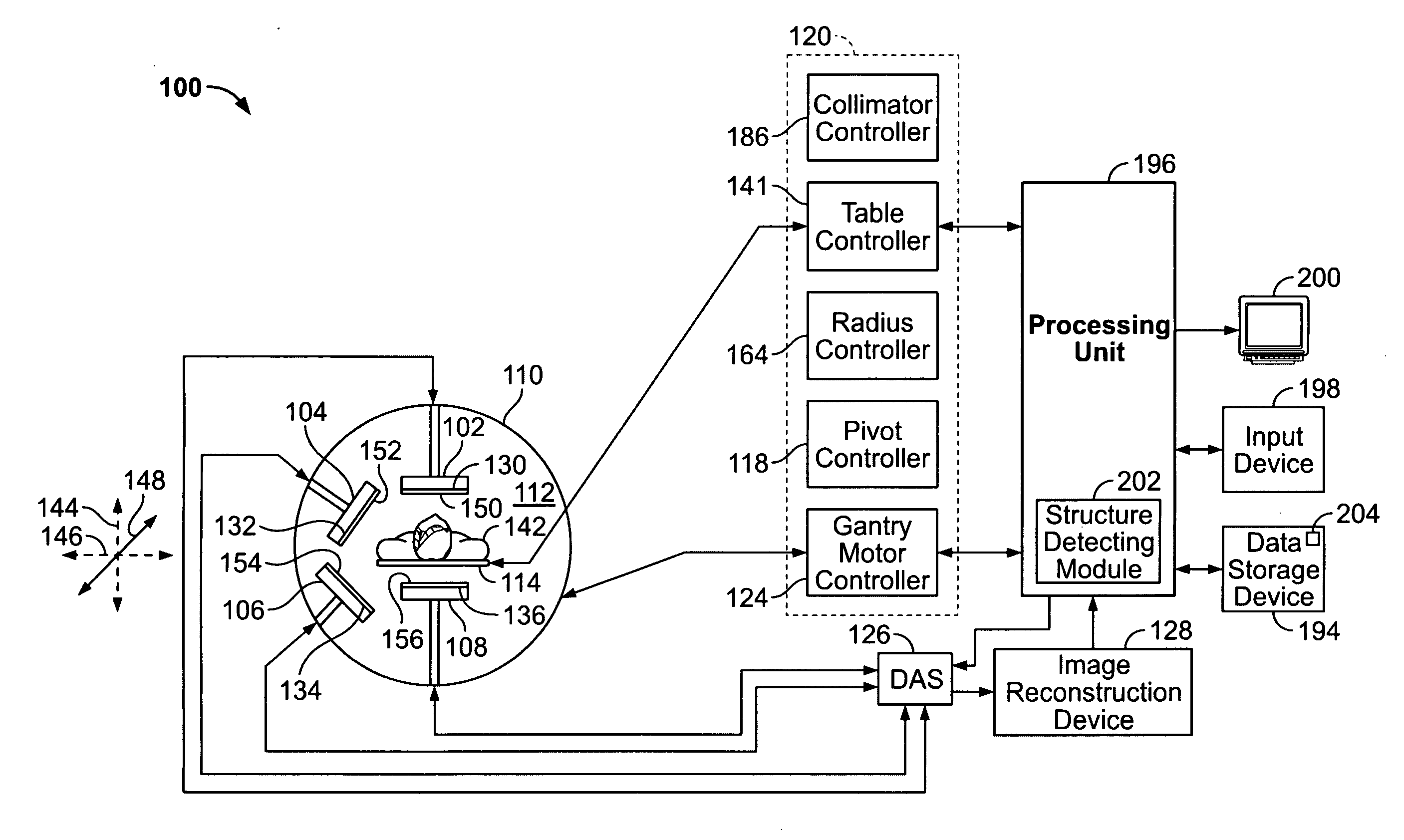
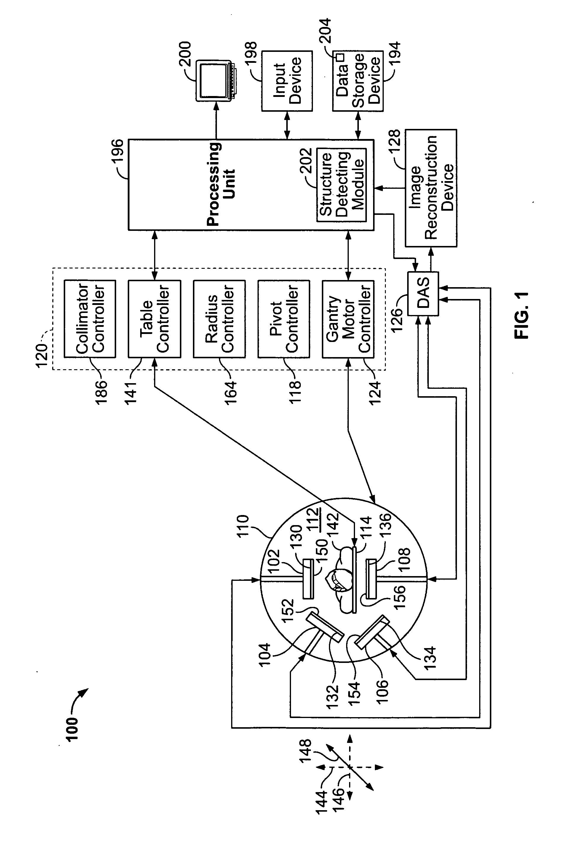
[0017]FIG. 1 is a schematic illustration of a Nuclear Medicine (NM) imaging system 100 which has a plurality of small imaging detectors mounted on a gantry. In FIG. 1, first, second, third through N imaging detectors 102, 104, 106 and 108 are mounted on a gantry 110. As illustrated in FIG. 1, N is equal to four; however, it should be understood that two, three or more than four imaging detectors may be used.

[0018]Each of the first through N imaging detectors 102-108 are smaller than a conventional imaging detector. A conventional imaging detector may be large enough to image most or all of a width of a patient's body at one time and may have a diameter of approximately 40 cm. In contrast, each of the first through N imaging detectors 102-108 may have dimensions of 4 cm to 20 cm and may be formed of cadmium zinc telluride (CZT) tiles. For example, each of the first through N imaging detectors 102-108 may be 8×8 cm in size and be composed of a plurality of CZT pixilated modules (not s...


PUM


Abstract

An apparatus for imaging a structure of interest comprises a plurality of imaging detectors mounted on a gantry. Each of the plurality of imaging detectors has a field of view (FOV), is independently movable with respect to each other, and is positioned to image a structure of interest within a patient. A data acquisition system receives image data detected within the FOV of each of the plurality of imaging detectors.

Description

BACKGROUND OF THE INVENTION[0001]This invention relates generally to nuclear medicine imaging, and more particularly, to efficiently imaging structures of interest with multiple imaging detectors having small fields of view.[0002]In nuclear medicine (NM) imaging, the time required to acquire a scan of a patient can be long, leading to patient discomfort. Furthermore, if the patient moves, the image may be degraded and the scan may need to be repeated. In addition to the cost of the equipment, a high cost of operation may also be realized due to the time and manpower required to operate the equipment. Large size imaging detectors also have limited maneuverability due to their geometry when positioned close to a patient.[0003]In some types of scans, such as when scanning the whole body or with large patients, the portion of the patient being imaged may require the entire field of view of a conventional large size imaging detector. However, when imaging a structure which is smaller tha...

Claims


Application Information

Patent Timeline
IPC IPC(8): G01T1/20
CPCA61B6/037A61B6/4266A61B6/06
Inventor HEFETZ, YARONBLEVIS, IRA
Owner GE HEALTHCARE ISRAEL
Why Eureka
Try Eureka