Gradient coil system and mr imaging system embodying same

a gradient coil and imaging system technology, applied in the field of gradient coil systems, can solve the problems of high labor intensity, high noise production of gradient coil systems during operation, and additional significant labor costs, and achieve the effect of easy and economical manufactur

Active Publication Date: 2008-02-07
SIEMENS HEALTHCARE GMBH
View PDF4 Cites 18 Cited by
  • Summary
  • Abstract
  • Description
  • Claims
  • Application Information

AI Technical Summary

Benefits of technology

[0011]An object of the present invention is to provide a gradient coil system that can be manufactured as easily and economically as possible. In addition, the gradient coil system should have a cooling that is as efficient as possible. In addition, an object of the present invention is to provide an improved magnetic resonance tomography apparatus having such a gradient coil system.

Problems solved by technology

In this way, at the same time the mechanical vibrations of the gradient coils during operation are damped, so that the production of noise by the gradient coil system during operation is relatively low.
Laying the cooling lines in a serpentine-like structure is very labor-intensive.
This means an additional significant labor outlay.
During the sewing, there is in addition the risk that a cooling line will be penetrated by a needle, and will thus develop a leak.
A single hole in a cooling line can make the entire gradient coil system unusable.

Method used


Image

  • Gradient coil system and mr imaging system embodying same
  • Gradient coil system and mr imaging system embodying same
  • Gradient coil system and mr imaging system embodying same

Examples


Embodiment Construction

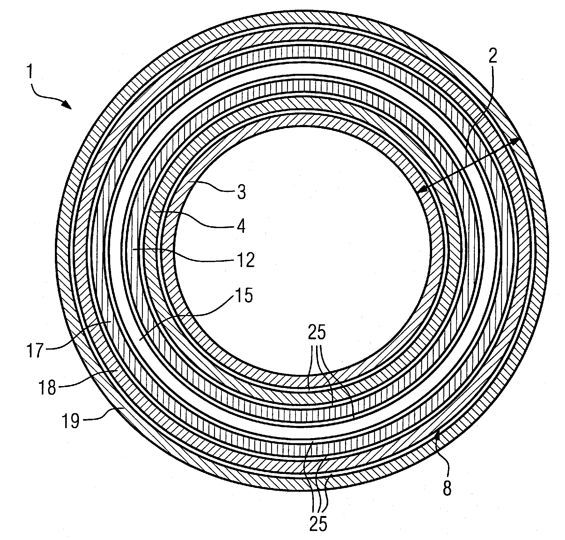
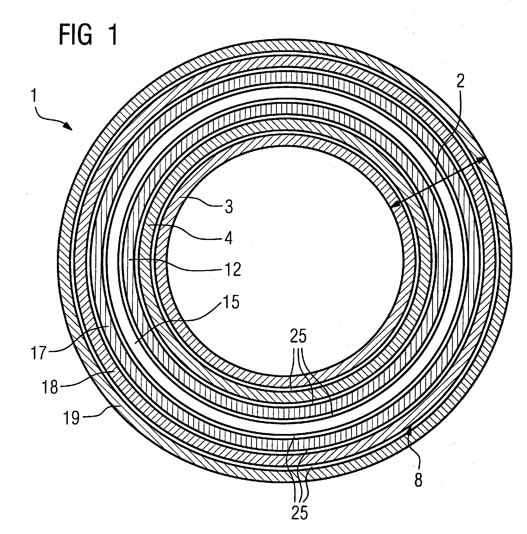
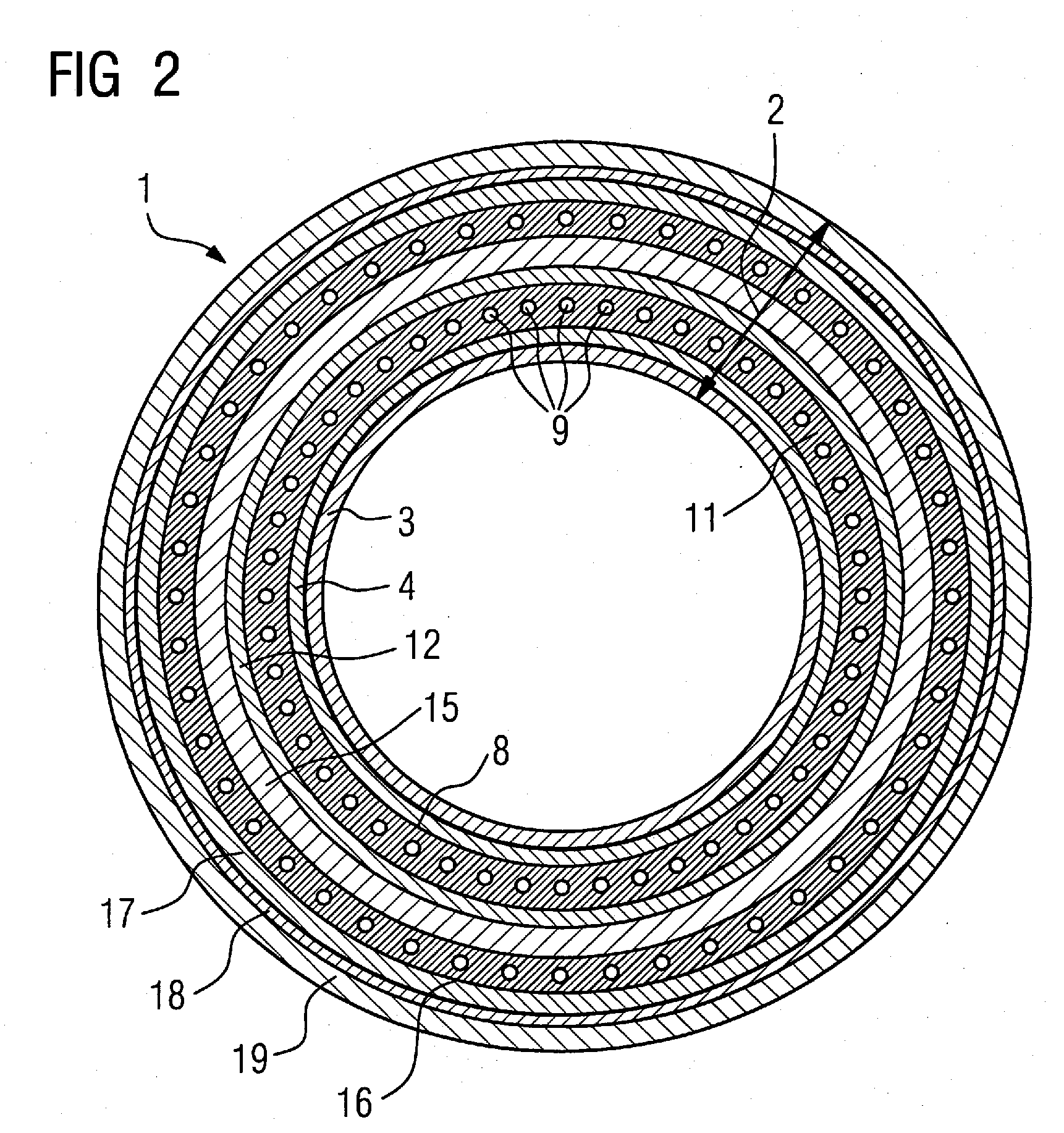
[0034]FIG. 2 shows a gradient coil system 1 according to the prior art. This gradient coil system 1 has a concentrically situated hollow cylindrical layer structure 2. The assembly of the individual layers of the layer structure takes place from the inside to the outside in the radial direction. The first hollow cylindrical layer is assembled to the jacket [or: covering] surface of a cylindrical assembly aid. The second layer is assembled to the outer jacket surface of the first layer, etc.

[0035]The innermost two layers are a first gradient coil layer 3 and a second gradient coil layer 4, for producing a respective transverse gradient magnetic field. The gradient coils built into these two gradient coil layers are saddle coils.

[0036]A first cooling layer 8 is connected thereto as the next layer. This layer is composed of cooling lines 9 arranged in a serpentine path around the outer jacket surface of second gradient coil layer 4, in order to conduct away the heat generated by the gr...


PUM

PropertyMeasurementUnit
internal angleaaaaaaaaaa
heightaaaaaaaaaa

Abstract

A gradient coil system for a magnetic resonance tomography apparatus has a layer structure including a gradient coil layer and a cooling layer. The cooling layer is fashioned as a plate heat exchanger, composed of plates, for cooling the gradient coil layer. In this way, a highly efficient cooling of the gradient coil layer is achieved with a lower structural height compared to conventional tubular configurations.

Description

BACKGROUND OF THE INVENTION[0001]1. Field of the Invention[0002]The present invention relates to a gradient coil system, in particular for a magnetic resonance tomography apparatus, having a gradient coil layer and a layer structure that includes a cooling layer.[0003]2. Description of the Prior Art[0004]In the operation of a magnetic resonance tomography apparatus, for image production it is necessary to superimpose at least one gradient magnetic field on the magnetic basic field. This is done using a gradient coil system. Conventionally, the gradient coil system has a number of gradient coil layers having one or more gradient coils in order to produce three gradient magnetic fields perpendicular to one another. In the actively shielded gradient coil systems used today, in addition to the gradient coil layers that produce the useful field additional gradient coil layers are provided that externally shield the useful field. These additional gradient coil, layers are situated around ...

Claims


Application Information

Patent Timeline
Patent Type & Authority Applications(United States)
IPC IPC(8): G01R33/44
CPCF28D9/0012F28D9/0087F28F3/086H01F27/2876G01R33/3856H01F27/10F28F21/065
Inventor GROMOLL, BERNDHUBER, NORBERTSCHUSTER, JOHANNSCHOEN, LOTHARSTOCKER, STEFAN
Owner SIEMENS HEALTHCARE GMBH
Why Eureka
Try Eureka