Monitor

Active Publication Date: 2008-02-07
PANASONIC CORP
View PDF24 Cites 13 Cited by
  • Summary
  • Abstract
  • Description
  • Claims
  • Application Information

AI Technical Summary

Benefits of technology

[0008] Another method of covering a wide (angular) range is scanning. Nevertheless, this method requires mechanical rotation, and hence causes an extremely large cost increase. Yet another method is a phased array antenna in which the antenna lobe is rotated electronically. Nevertheless, in order to achie

Problems solved by technology

This causes the problem of an increase in the overall system cost.
Nevertheless, this method requires mechanical rotation, and hence causes an extremely large cost increase.
This ca

Method used


Image

  • Monitor
  • Monitor
  • Monitor

Examples


Example

Embodiment 1

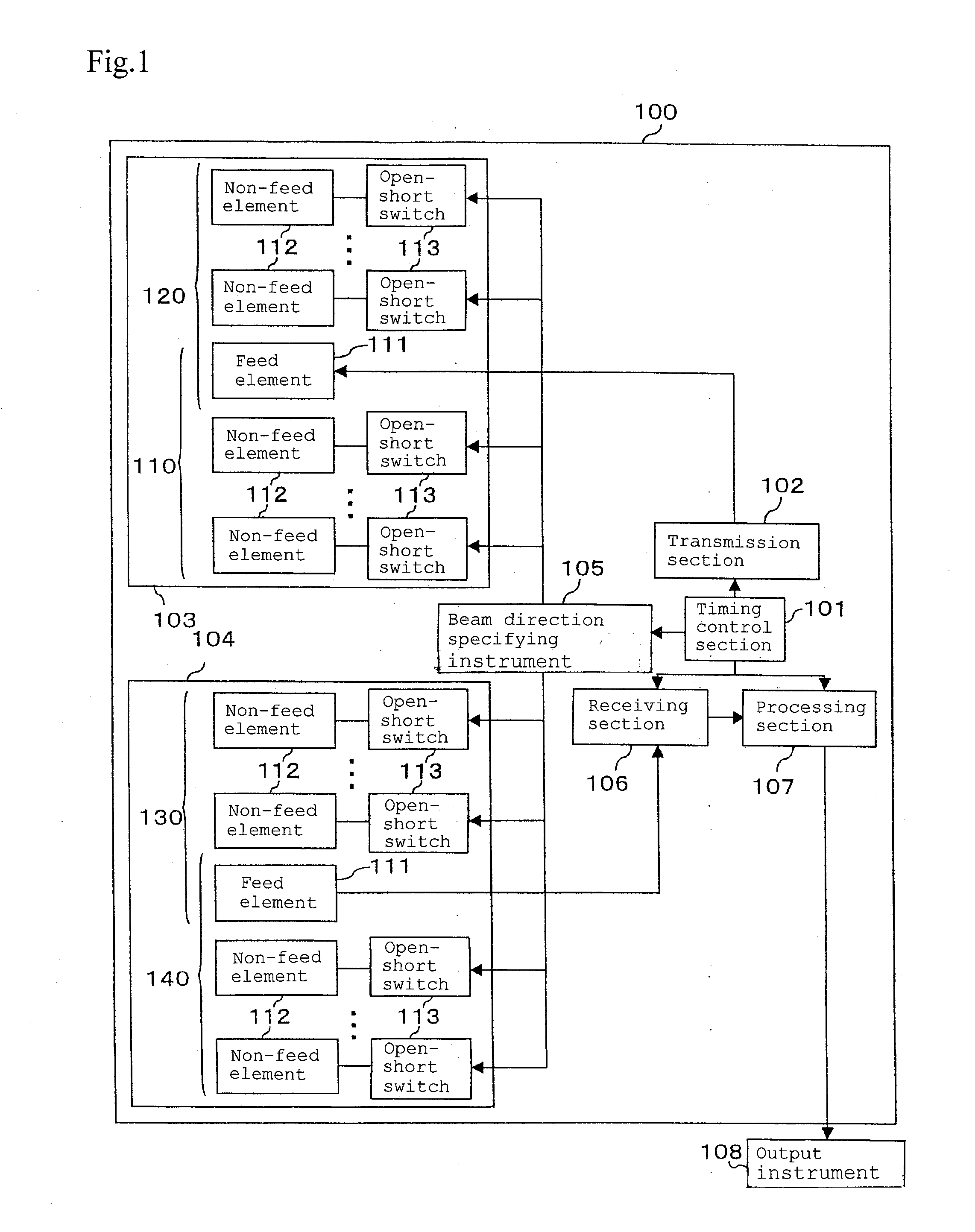
[0117]FIG. 1 is a block configuration diagram of a vehicle surroundings monitoring apparatus according to Embodiment 1 of the present invention.

[0118] In FIG. 1, a vehicle surroundings monitoring apparatus 100 comprises: a timing control section 101; a transmission section 102 of transmitting a radio wave; a transmission antenna 103 having a plurality of beams; a receiving antenna 104; beam direction specifying instrument 105 which switches the beam direction of the antenna; a receiving section 106 of receiving a reflection signal; and a processing section 107. The transmission section 102, the beam direction specifying instrument 105, the receiving section 106, and the processing section 107 are controlled on the basis of timing signals from the timing control section 101. Here, the vehicle surroundings monitoring apparatus 100 is an example of the monitoring apparatus of the present invention. The transmission antenna 103 and the receiving antenna 104 are examples of...

Example

Embodiment 2

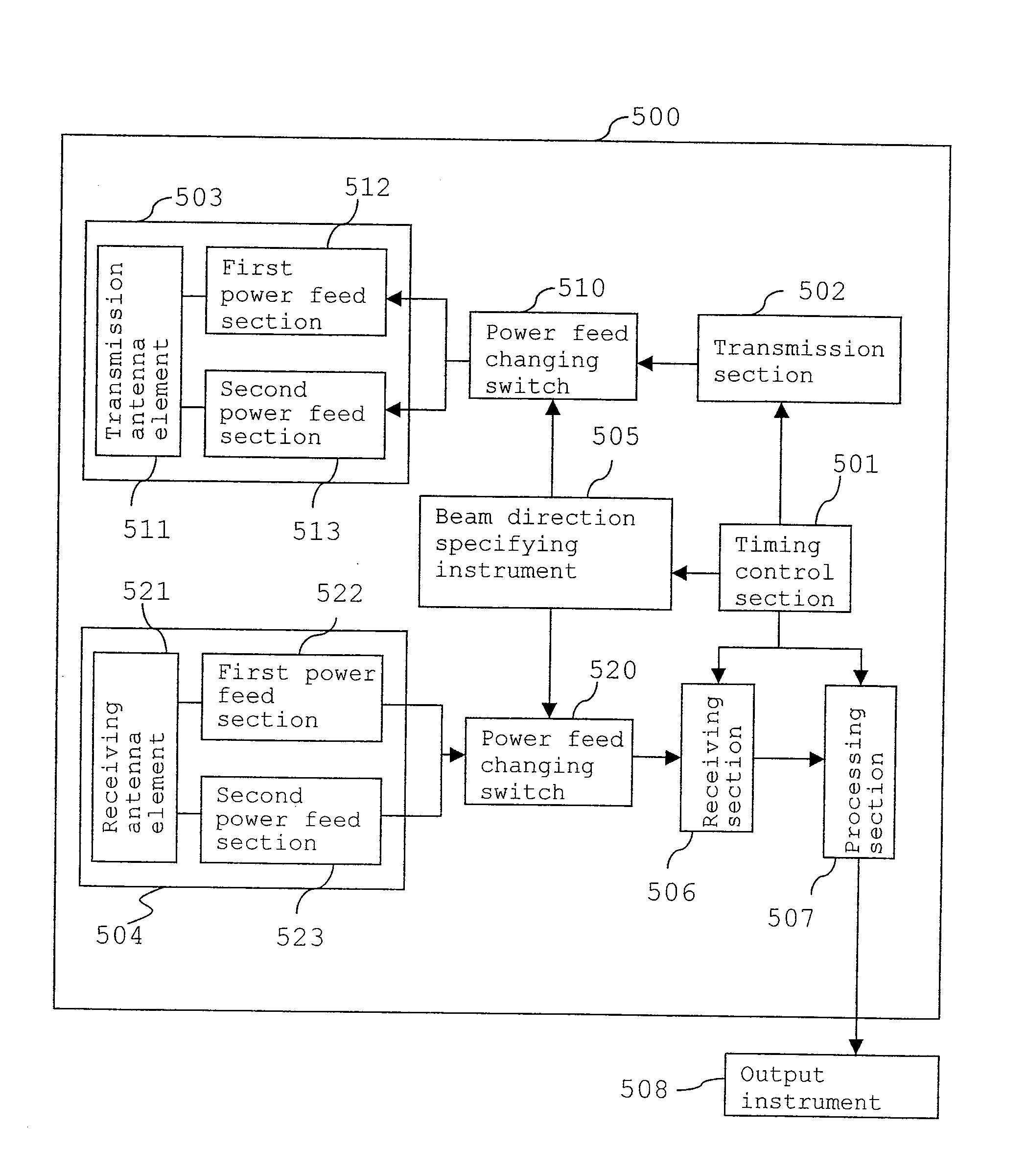
[0158]FIG. 8 is a block configuration diagram of a vehicle surroundings monitoring apparatus according to Embodiment 2 of the present invention.

[0159] The vehicle surroundings monitoring apparatus 500 of the present Embodiment 2 has a configuration different from that of the vehicle surroundings monitoring apparatus 100 of Embodiment 1 shown in FIG. 1 in the point that each of the transmission antenna and the receiving antenna has a plurality of power feed ports while power feed to the power feed ports is switched so that a plurality of beam directions are realized. Here, the vehicle surroundings monitoring apparatus 500 is an example of the monitoring apparatus of the present invention.

[0160] A timing control section 501, a transmission section 502, a receiving section 506, a processing section 507, and an output instrument 508 shown in FIG. 8 have respectively the same function as the timing control section 101, the transmission section 102, the receiving section 10...

Example

Embodiment 3

[0199]FIG. 16 is a block configuration diagram of a vehicle surroundings monitoring apparatus 1650 according to Embodiment 3 of the present invention.

[0200] The vehicle surroundings monitoring apparatus 1650 of the present Embodiment 3 differs from the vehicle surroundings monitoring apparatus 500 of Embodiment 2 shown in FIG. 8 in the point that running status information storing section 1600 of storing running state information of a vehicle is provided. In FIG. 16, like components to FIG. 8 are designated by like numerals, and hence description is omitted. Here, the running status information storing section 1600 is an example of the running information storing section of the present invention.

[0201] The running status information storing section 1600 stores running state information of a vehicle obtained from a vehicle speed sensor 1601, a steering angle sensor 1602, and a switch 1603 such as a turn indicator provided in the vehicle. Then, on the basis of the runni...


PUM


Abstract

A monitoring apparatus of the present application comprises: a transmission antenna section for sending out a radio wave of single beam having a wide angle or alternatively a radio wave having a narrower (angular) range in a plurality of beam directions; a receiving antenna section for receiving the radio wave in a plurality of beam directions transmitted by the transmission antenna section and then reflected by the target and for having a first power feed section and a second power feed section; a transmission section for transmitting to the transmission antenna section a signal to be sent out as the radio wave; a receiving section to which the radio wave received by the receiving antenna section is transmitted as a signal from the receiving antenna section ; and beam switching instrument which performs a switching operation such that power should be fed to either the first power feed section or the second power feed section, which thereby forms the beam directions of two radio waves, and which thereby controls a monitoring area.

Description

CROSS-REFERENCE TO RELATED APPLICATIONS [0001] This application is a U.S. national phase application of PCT International Patent Application No. PCT / JP2005 / 16952, filed Sep. 14, 2005, claiming the benefit of priority of Japanese Patent Application Nos. 2004-268615 filed Sep. 15, 2004 and 2005-056484 filed Mar. 1, 2005, all of which are incorporated by reference herein in their entirety.TECHNICAL FIELD [0002] The present invention relates to a monitoring apparatus for sending out a radio wave, then receiving a reflected reflection signal, and thereby detecting a material body, a person, and the like in the surroundings. BACKGROUND ART [0003] In an example of a prior art vehicle surroundings monitoring apparatus for monitoring the surroundings of a vehicle, an ultrasonic sensor is attached at a corner of the front or the rear of the vehicle so that a surrounding obstacle is detected or its distance is measured. Then, in case of danger of contact, the situation is reported to the drive...

Claims


Application Information

Patent Timeline
IPC IPC(8): G01S13/93G01S7/02G01S5/14G01S13/931
CPCG01S13/931G01S2013/9389H01Q1/3233H01Q1/3283H01Q3/247H01Q3/446H01Q7/00H01Q13/106H01Q19/24G01S2013/9332G01S2013/9353G01S2013/9375G01S2013/9378G01S2013/9385G01S2013/9371G01S2013/9327G01S2013/9315G01S2013/93275G01S2013/93274G01S2013/93272G01S2013/93271G01S2013/932
Inventor YOSHIDA, TAKASHI
Owner PANASONIC CORP
Why Eureka
Try Eureka