Planar light-source apparatus

a light source and apparatus technology, applied in the direction of illuminated signs, instruments, display means, etc., can solve the problems of uneven brightness of diffusing plates, damage to braces, and generation of dust (dirt and powder) to achieve the effect of improving the quality of displayed images

Active Publication Date: 2008-02-07
SATURN LICENSING LLC
View PDF2 Cites 29 Cited by
  • Summary
  • Abstract
  • Description
  • Claims
  • Application Information

AI Technical Summary

Benefits of technology

[0008] Accordingly, it is desirable to provide a planar light-source apparatus having a structure in that a member for supporting a diffusing plate is difficult to be damaged as well as difficult to generate dust (dirt and powder).
[0031] The region of the transparent first electrode overlapping with those of the transparent second electrode and the liquid crystal cell corresponds to one pixel or one sub-pixel. In the transmissive color liquid crystal display, a red-luminous sub-pixel (sub-pixel [R]) is composed of combinations of such a region and a red-transmissive color filter; a green-luminous sub-pixel (sub-pixel [G]) is composed of combinations of such a region and a green-transmissive color filter; and a blue-luminous sub-pixel (sub-pixel [B]) is composed of combinations of such a region and a blue-transmissive color filter. The arrangement pattern of the sub-pixel [R], the sub-pixel [G], and the sub-pixel [B] agrees with that of the color filters mentioned above. The pixel is not limited to the configuration forming a group of every three sub-pixels [R], [G], and [B], so that the pixel may be configured by forming a group of one or a plurality of sub-pixels added to the three sub-pixels. For example, there may be one group added by a white luminous sub-pixel for improving the luminance, one group added by a complementary color luminous sub-pixel for extending the color reproduction range, one group added by a yellow luminous sub-pixel for extending the color reproduction range, and one group added by yellow and cyan luminous sub-pixels for extending the color reproduction range.
[0034] Furthermore, in the planar light-source apparatus according to the embodiment of the present invention, in order to obtain the pixel luminance (the second reference value y2 of the display luminance in the first reference value Lt1 of the light transmittance) when it is assumed that the control signal value be supplied to the pixel, the control signal value being equivalent to the drive signal maximum value xU-max in the display area unit, the luminance of the light-source constituting the planar light-source unit corresponding to the display area unit is controlled in the drive circuit, so that not only the power consumption of the planar light-source apparatus can be reduced, but also the white level is increased and the black level is reduced so as to obtain the high contrast ratio (the luminance ratio between the whole black display portion and the whole white display portion, which does not include outside light reflection, in the picture surface of the liquid crystal display). Thereby, the emphasis of the desired brightness of the display area is enabled, improving quality of displayed images.

Problems solved by technology

However, in a supporting structure of the diffusing plate with such a brace, during manufacturing and transporting the planar light-source apparatus or during assembling the planar light-source apparatus with the liquid crystal display and transporting their assembly, when an excessive force is applied to the brace, the brace may be damaged.
Since the diffusing plate and the brace are made of plastics, dust (dirt and powder) may also be generated due to the contact between both the members.
Furthermore, another problem may arise that uneven brightness of the diffusing plate is generated due to the shadow of the brace.

Method used


Image

  • Planar light-source apparatus
  • Planar light-source apparatus
  • Planar light-source apparatus

Examples


first embodiment

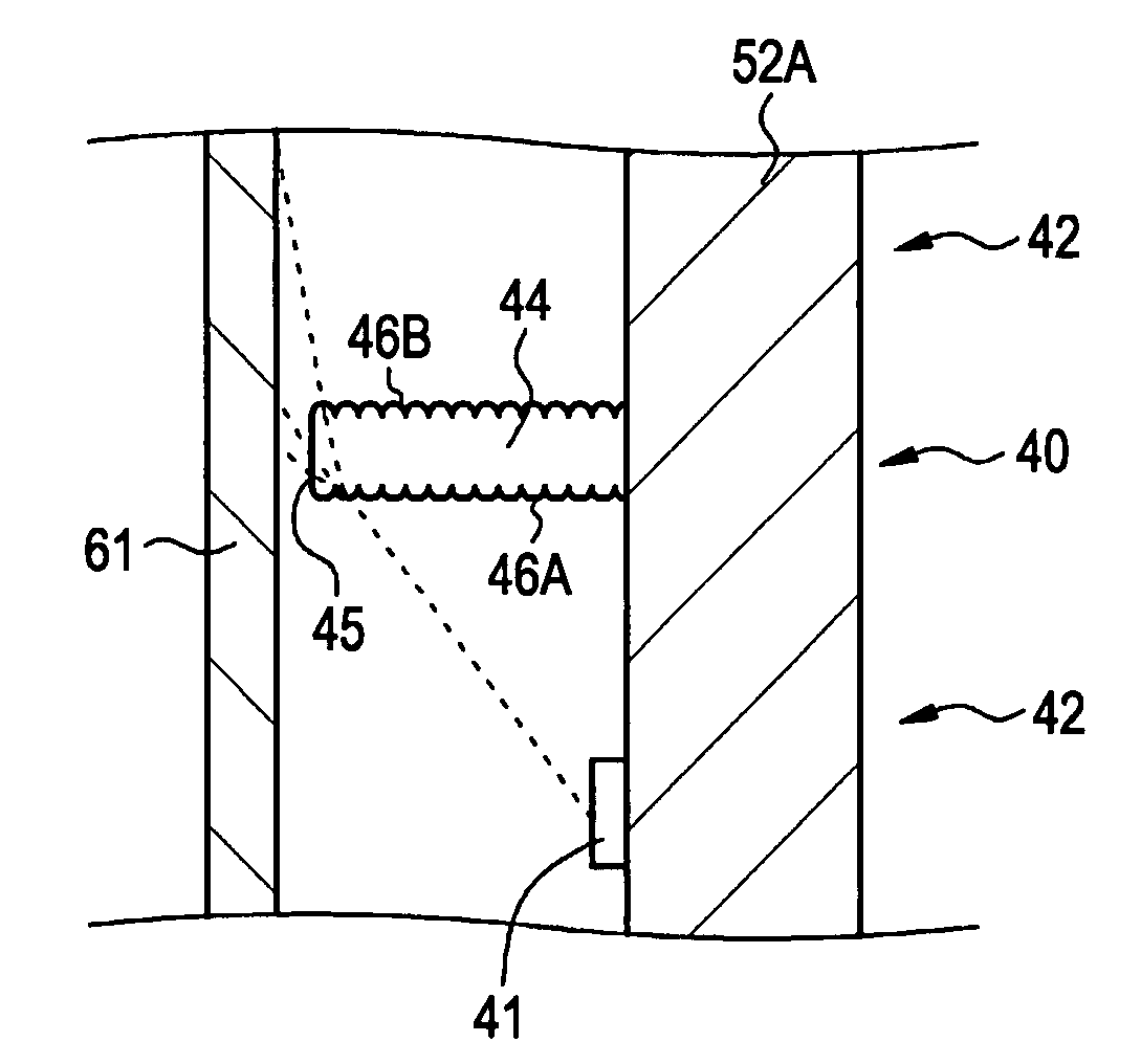
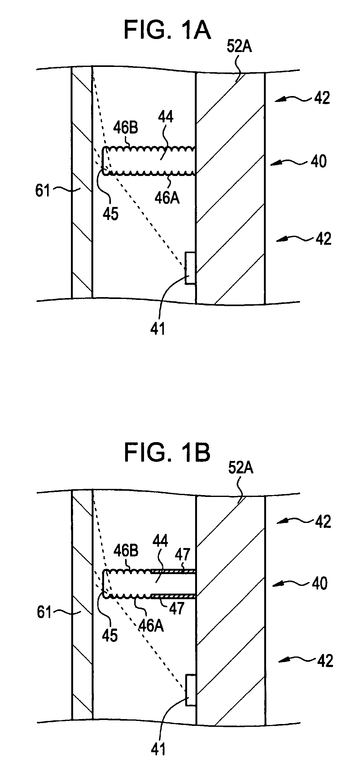
[0059] A first embodiment of the present invention relates to a planar light-source apparatus. FIG. 1A is a conceptual diagram of part of the planar light-source apparatus according to the first embodiment. The planar light-source apparatus 40 according to the first embodiment illuminates the transmissive color liquid crystal display 10 from the backside, which includes the display area 11 composed of pixels formed in a two-dimensional matrix arrangement. The planar light-source apparatus 40 according to the first embodiment includes the diffusing plate 61 opposing the color liquid crystal display 10 and a plurality of the planar light-source units 42. Each planar light-source unit 42 includes the light-emitting sources 41 (41R, 41G, 41B), and between the planar light-source units 42, the support wall 44 is arranged for supporting the diffusing plate 61, and the top face 45 of the support wall 44 is arranged close to the diffusing plate 61.

[0060] Specifically, as shown in FIG. 1A, ...

second embodiment

[0085] A second embodiment is a modification of the first embodiment. According to the second embodiment, as shown in the conceptual partial diagram of FIG. 1B, the unevenness is formed on upper parts of the first side 46A and the second side 46B of the support wall 44 while a light reflection layer 47 is formed on the residual parts of the first side 46A and the second side 46B of the support wall 44. More specifically, the silver-added reflection film formed by sequentially laminating a silver reflection film, a low refractive-index film, and a high refractive-index film may be bonded with an adhesive on the residual parts of the first side 46A and the second side 46B of the support wall 44.

third embodiment

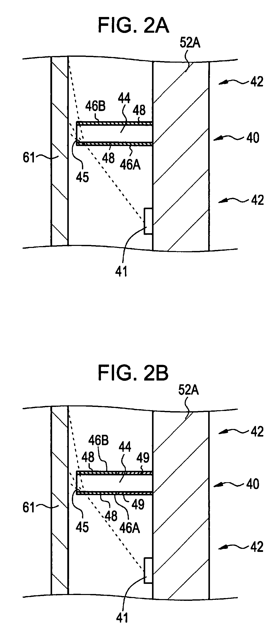
[0086] A third embodiment is also a modification of the first embodiment. According to the third embodiment, in the same way as in the first embodiment, the support wall 44 is made of a material transparent to the light emitted from the light-emitting source 41 provided in the planar light-source unit 42. However, differently from the first embodiment, as shown in the conceptual partial diagram of FIG. 2A, on at least upper parts (more specifically whole faces) of the first side 46A and the second side 46B of the support wall 44, a light-transmissive diffusing film 48 is bonded with an adhesive.


PUM

PropertyMeasurementUnit
thicknessaaaaaaaaaa
wavelengthaaaaaaaaaa

Abstract

A planar light-source apparatus illuminates, from the backside, a transmissive liquid crystal display having a display area composed of pixels formed in a two-dimensional matrix arrangement, and the planar light-source apparatus includes a diffusing plate facing the liquid crystal display, a plurality of planar light-source units, each unit having a light source, and a support wall arranged between the planar light-source units for supporting the diffusing plate, and the top face of the support wall lies adjacent to the diffusing plate.

Description

CROSS REFERENCES TO RELATED APPLICATIONS [0001] The present invention contains subject matter related to Japanese Patent Application JP 2006-154982 filed in the Japanese Patent Office on Jun. 2, 2006, the entire contents of which are incorporated herein by reference. BACKGROUND OF THE INVENTION [0002] 1. Field of the Invention [0003] The present invention relates to a planar light-source apparatus. [0004] 2. Description of the Related Art [0005] In a liquid crystal display, a liquid crystal material itself does not emit light. Hence, a direct-lighting type planar light-source apparatus (backlight) is arranged on the back of a display area, composed of a plurality of pixels, of a liquid crystal display for illuminating the display area (see Nikkei Electronics No. 889, Dec. 20, 2004, p123 to 130). In a color liquid crystal display, one pixel is composed of a red-luminous sub-pixel, a green-luminous sub-pixel, and a blue-luminous sub-pixel. A liquid crystal cell constituting a pixel or...

Claims


Application Information

Patent Timeline
Patent Type & Authority Applications(United States)
IPC IPC(8): G02F1/13357
CPCG02F1/133603G02F1/133609G02F1/133611G02F2201/58G09G3/3413G09G3/3426G09G2360/16G09G2320/0242G09G2320/029G09G2320/041G09G2320/064G09G2360/145G09G2320/0233
Inventor MORITA, MASAYOSHIMORIMOTO, TADASHI
Owner SATURN LICENSING LLC
Why Eureka
Try Eureka