Optical transmitter and optical transmission system
- Summary
- Abstract
- Description
- Claims
- Application Information
AI Technical Summary
Benefits of technology
Problems solved by technology
Method used
Image
Examples
first embodiment
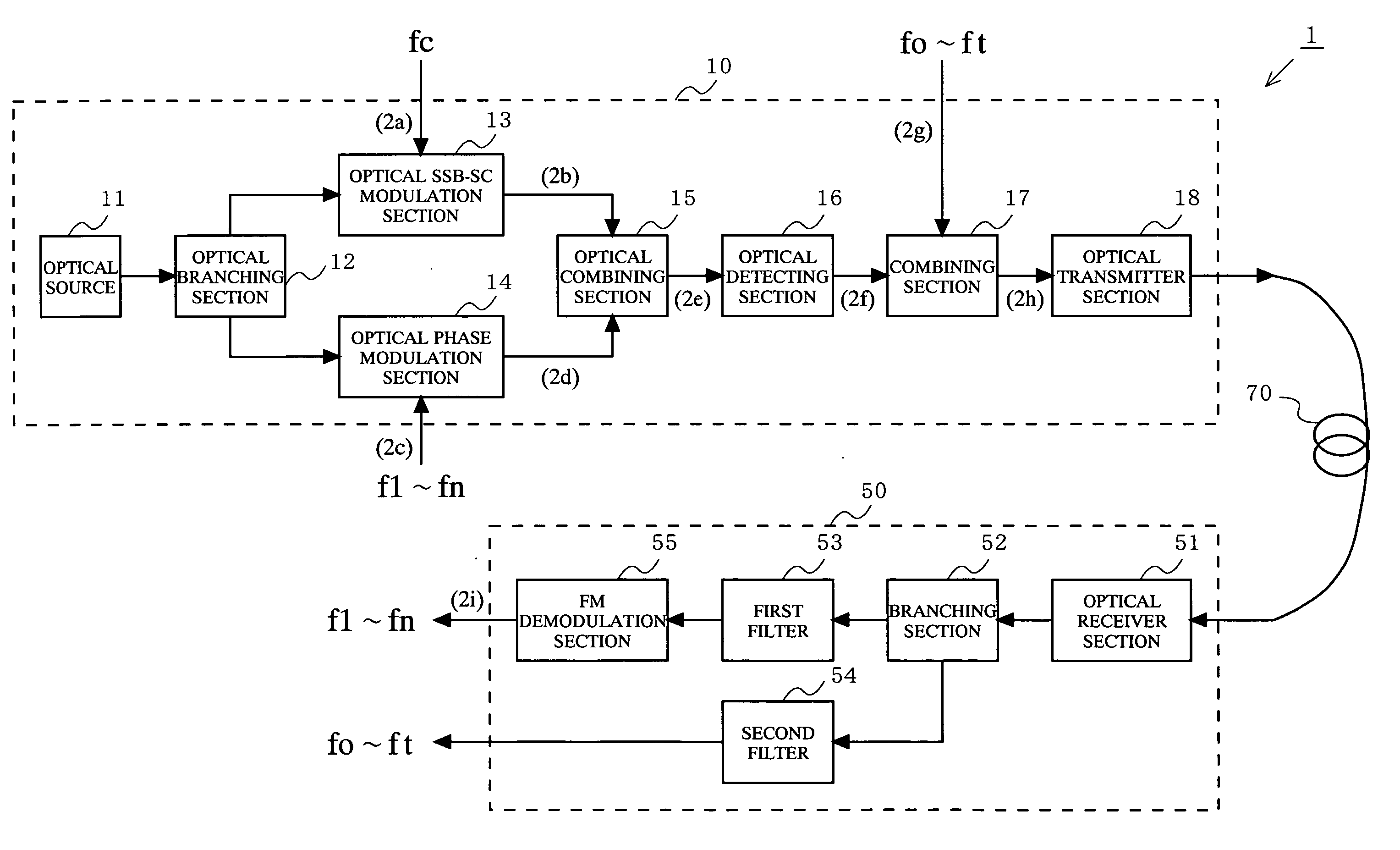
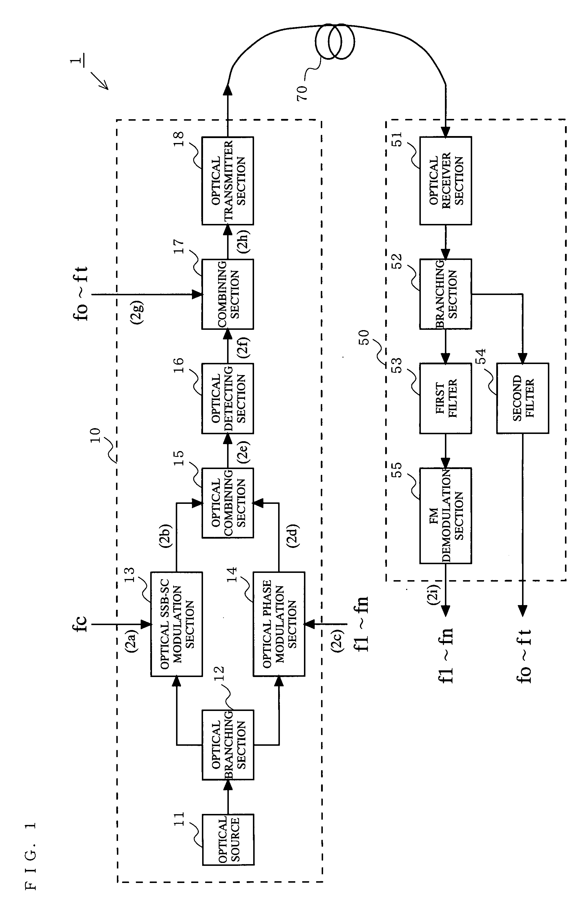
[0039]FIG. 1 is a block diagram showing a configuration of an optical transmission system 1 according to a first embodiment of the present invention. The optical transmission system 1 includes an optical transmitter 10 and an optical receiver 50 connected to each other via an optical fiber 70. The optical transmitter 10 includes an optical source 11, an optical branching section 12, an optical intensity modulation section 13, an optical phase modulation section 14, an optical combining section 15, an optical detecting section 16, a combining section 17, and an optical transmitter section 18. The optical receiver 50 includes an optical receiver section 51, a branching section 52, first and second filters 53 and 54, and an FM demodulation section 55. The optical intensity modulation section 13 used in the optical transmission system 1 will be referred to as the optical SSB-SC modulation section 13 because it performs an optical SSB-SC modulation.
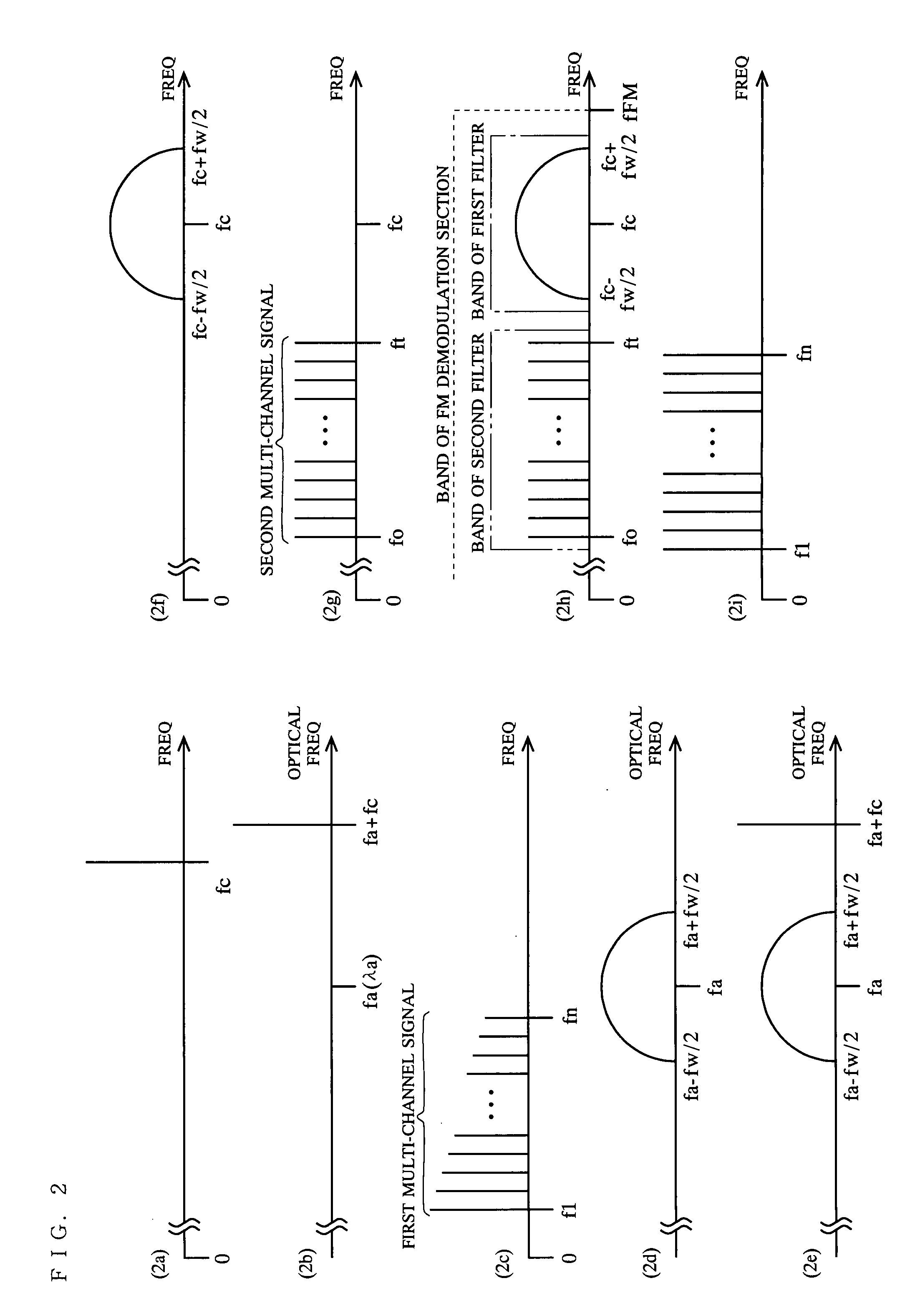
[0040]FIG. 2 is a schematic diagram sho...
second embodiment
[0060]FIG. 6 is a block diagram showing a configuration of an optical transmission system 2 according to a second embodiment of the present invention. The optical transmission system 2 includes an optical transmitter 20 and the optical receiver 50 connected to each other via the optical fiber 70. The optical transmitter 20 includes the optical source 11, the optical branching section 12, the optical SSB-SC modulation section 13, a multiplier section 21, a first filter 22, the optical phase modulation section 14, the optical combining section 15, the optical detecting section 16, a second filter 23, and the optical transmitter section 18. The configuration of the optical receiver 50 is the same as that of the first embodiment.
[0061]FIG. 7 is a schematic diagram showing exemplary signal spectra at different locations (7a to 7f) in the optical transmission system 2.
[0062]The optical transmission system 2 of the second embodiment differs from the optical transmission system 1 of the fir...
third embodiment
[0071]FIG. 8 is a block diagram showing a configuration of an optical transmission system 3 according to a third embodiment of the present invention. The optical transmission system 3 includes an optical transmitter 30 and the optical receiver 50 connected to each other via the optical fiber 70. The optical transmitter 30 includes the optical source 11, the optical branching section 12, the optical SSB-SC modulation section 31, the optical phase modulation section 14, the optical combining section 15, the optical detecting section 16, the filter 23, and the optical transmitter section 18. The configuration of the optical receiver 50 is the same as those of the first and second embodiments.
[0072]The optical transmission system 3 of the third embodiment differs from the optical transmission system 2 of the second embodiment in that the multiplier section 21, the first filter 22 and the optical SSB-SC modulation section 13 are replaced by the optical SSB-SC modulation section 31. Thus,...
PUM
 Abstract
Description
Claims
Application Information
 - R&D
- Intellectual Property
- Life Sciences
- Materials
- Tech Scout
- Unparalleled Data Quality
- Higher Quality Content
- 60% Fewer Hallucinations
Browse by: Latest US Patents, China's latest patents, Technical Efficacy Thesaurus, Application Domain, Technology Topic, Popular Technical Reports.
© 2025 PatSnap. All rights reserved.Legal|Privacy policy|Modern Slavery Act Transparency Statement|Sitemap|About US| Contact US: help@patsnap.com


