Combination Conveyor Oven

a conveyor oven and oven technology, applied in ovens, baking ovens, lighting and heating apparatus, etc., can solve the problems of reducing the useful life of ceramic heating elements, unsuitable oven types for broader applications, and ruining food products, so as to achieve the effect of conserving energy

Inactive Publication Date: 2008-02-07
NU VU FOOD SERVICE SYST
View PDF12 Cites 41 Cited by
  • Summary
  • Abstract
  • Description
  • Claims
  • Application Information

AI Technical Summary

Benefits of technology

[0010] According to a second aspect, a method for warming an oven with a conveyor and a plurality of ceramic heating elements is provided comprising the steps of providing electrical power to a controller and a plurality of heating elements and providing electrical power to the plurality of heating elements until the plurality of heating elements reach a first intermediate temperature. The steps of maintaining the plurality of heating elements at the first intermediate temperature for a first predetermined time period and providing electrical power to the plurality of heating elements until the plurality of heating elements reach a second intermediate temperature greater than the first intermediate temperature are also provided. Finally the method includes the steps of maintaining the plurality of heating elements at the second intermediate temperature for a second predetermined time period and providing electrical power to the plurality of heating elements until the plurality of heating elements reach a selected temperature, and maintaining the plurality of heating elements at the selected temperature.
[0011] According to a third aspect, a method for conserving energy used by a conveyor oven with a housing substantially enclosing the oven and a plurality of heating elements provided within the housing is provided. The method comprises the steps of providing a sensor located near an inlet opening of the housing that is operatively connected with the controller and connecting the controller to the plurality of heating elements to control the amount of current flowing to the heating elements. Further, the method includes the steps of lowering the amount of current from a reduced predetermined amount to a portion of the plurality of heating elements when the sensor does not detect a product on the conveyor for a selected period of time and increasing the current to predetermined amount to the portion of the plurality of heating elements when the sensor detects a product moving along the conveyor through the inlet opening.

Problems solved by technology

Although suitable for baking certain types of dough products, the moisture rich saturated steam makes this type of oven unsuitable for broader applications, namely the cooking of other types of food products, such as full sandwiches, vegetables and pizza.
The high moisture content within a steam-based oven can significantly wet the exterior surfaces of the sandwich or the pizza, ruining the food products.
A problem in ovens with ceramic heating elements is that in moisture-rich environments, the heating elements have a tendency to crack or otherwise brittle fracture, which reduces the useful life of a ceramic heating element.
If the heaters rapidly warm, the moisture may boil before it has time to migrate out of the heater.
The boiling of the moisture causes rapid expansion and increases the pressure within the gap, which may cause cracking or fracture.
It takes a significant amount of time and energy to heat a typical conveyor type oven to normal operating temperature, and when the oven is operating at normal temperature, the oven requires a significant amount of energy to operate.
As can be understood, and has been experienced by many restaurant industry employees, the elevated temperatures of the external surfaces of the oven may lead to burns if the employee's exposed skin contacts the oven's external surface during operation.

Method used


Image

  • Combination Conveyor Oven
  • Combination Conveyor Oven
  • Combination Conveyor Oven

Examples


Embodiment Construction

[0021] Although the following detailed description is focused on a conveyor-type oven, the embodiments discussed below can be successfully implemented in other types of ovens or heating apparatuses.

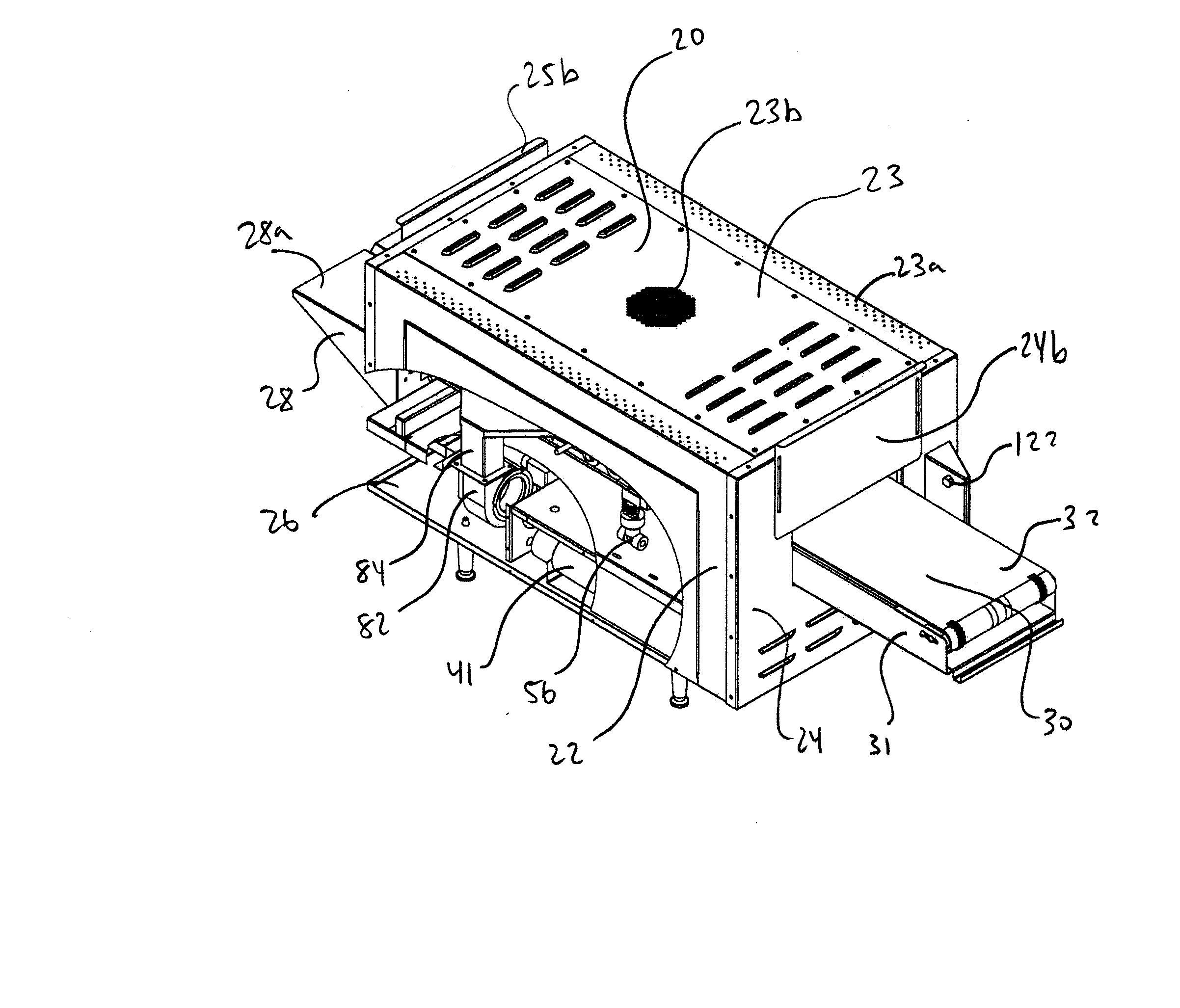
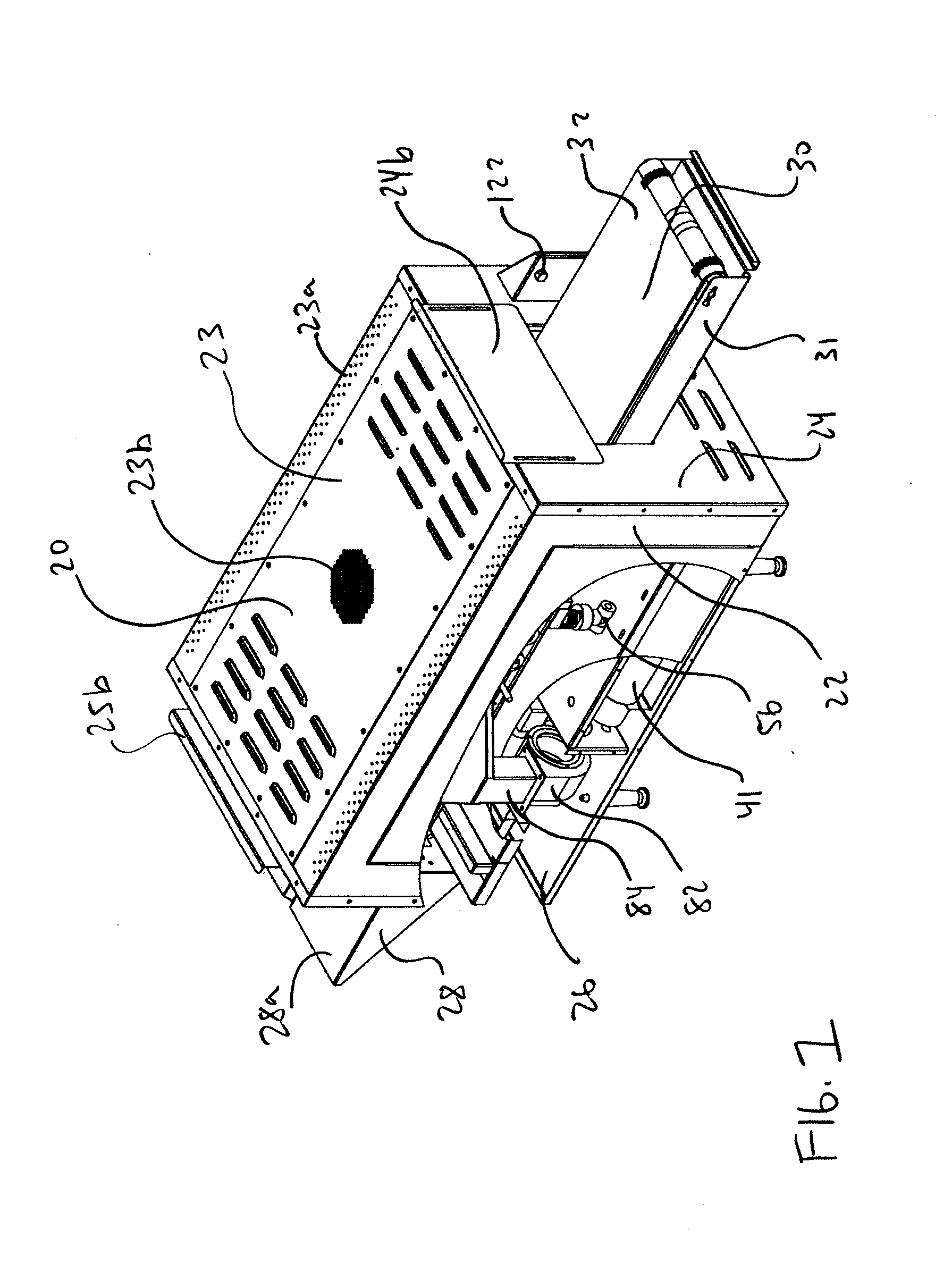
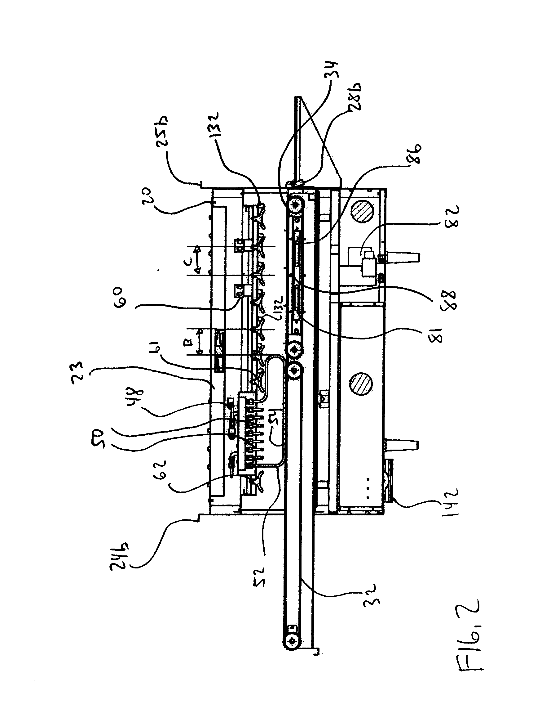
[0022] Turning now to FIGS. 1-6, a combination conveyor oven 10 is provided. Generally, the oven 10 includes a housing 20, a conveyor system 30, a steam system 40, a radiant heating system 60, and a forced convection system 80. Each of the steam system 40, the radiant heating system 60, and the forced convection system 80 are operatively controlled by a controller 124 that is provided within the housing 20 and operates each of the components based on the operating condition of the oven 10 as well as signals from a plurality of sensors provided within the oven 10. Accordingly, by selective operation of each of the steam system 40, the radiant heating system 60, and the forced convection system 80, a food product 12 may be fully cooked or toasted within the time it takes the food product 1...


PUM


Abstract

An oven for heating a product is provided. The oven includes a partially enclosed housing with an inlet opening and an outlet opening and a conveyor to move a product through the housing. The oven additionally includes a steam system for boiling liquid with an associated steam pipe and a heating element provided within the housing.

Description

[0001] This application claims priority from U.S. Provisional Application No. 60 / 801,831, filed on May 19, 2006, the entirety of which is hereby full incorporated herein by reference.TECHNICAL FIELD [0002] The present disclosure relates to the field of ovens to heat food products. Specifically, the present disclosure relates to conveyor ovens used to heat food products. BACKGROUND [0003] It is known in the art to provide an open ended oven with a moving conveyor belt that extends through the oven to move a food product through the oven. A typical conveyor oven includes a plurality of radiant heating elements located within the oven to provide a significant heat source to cook a food product that rides through the oven on the conveyor. [0004] Other types of conveyor ovens bake a food product made from dough by adding steam to the stream of hot air and imparting the mixture upon the product as it moves through the oven on a conveyor. This type of oven includes two open ends that are c...

Claims


Application Information

Patent Timeline
Patent Type & Authority Applications(United States)
IPC IPC(8): A21B1/36A23L1/01A23L5/10
CPCA21B1/48A47J37/044A21B3/04
Inventor GARNISS, RUSSELLDEMING, MATTHEWMAALOUF, NAJIB H.
Owner NU VU FOOD SERVICE SYST
Why Eureka
Try Eureka