
Device and Process for Plasma Coating/Sterilization

a technology for plasma coating and container, applied in packaging sterilization, disinfection, energy-based chemical/physical/physico-chemical processes, etc., can solve the problems of large mechanical complexity and inaccurate distribution of coating on irregularly shaped bottle bodies, and achieve simple design for conveyance and increase comparison efficiency

Inactive Publication Date: 2008-02-07
KRONES AG
View PDF23 Cites 26 Cited by
  • Summary
  • Abstract
  • Description
  • Claims
  • Application Information

AI Technical Summary

Benefits of technology

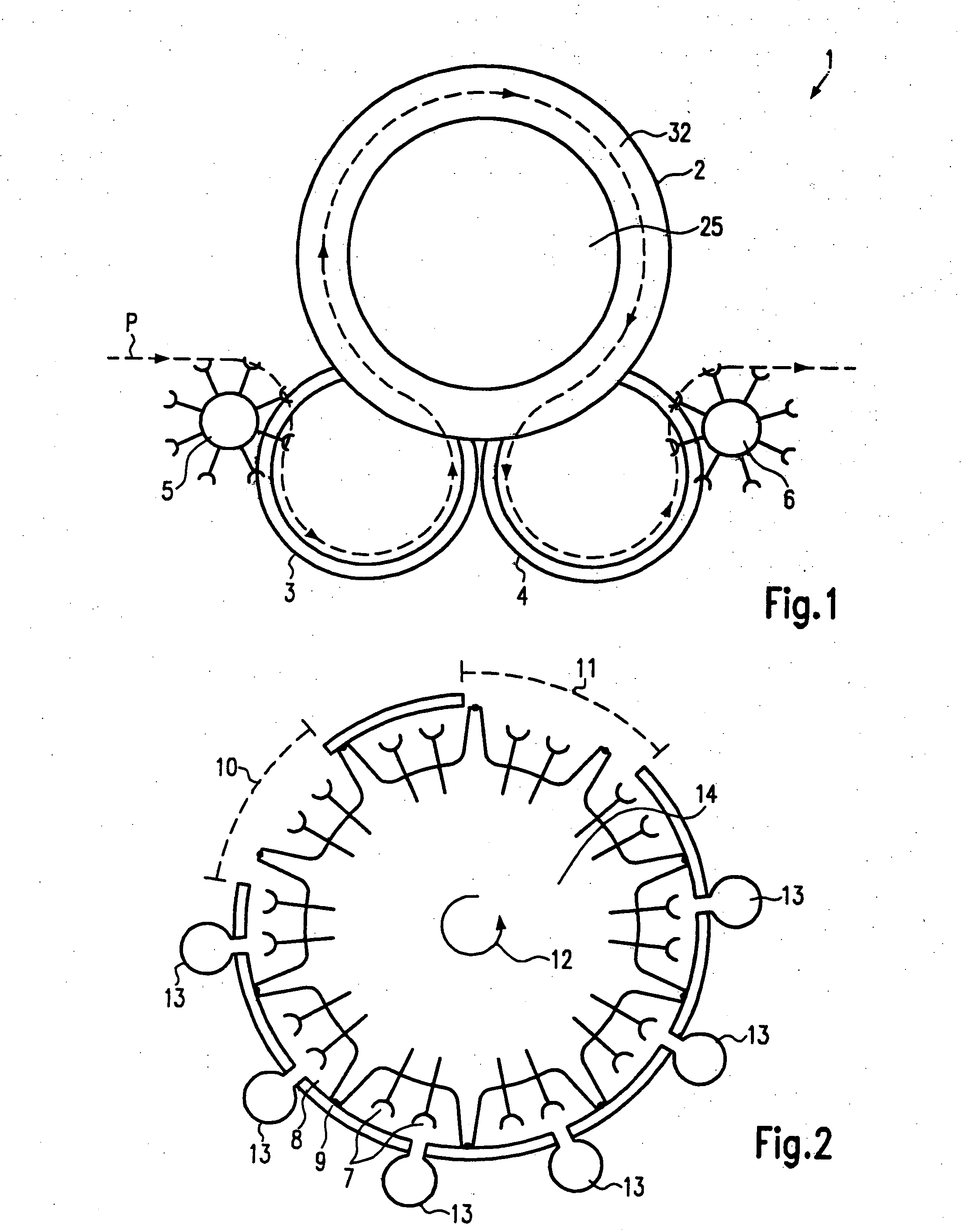
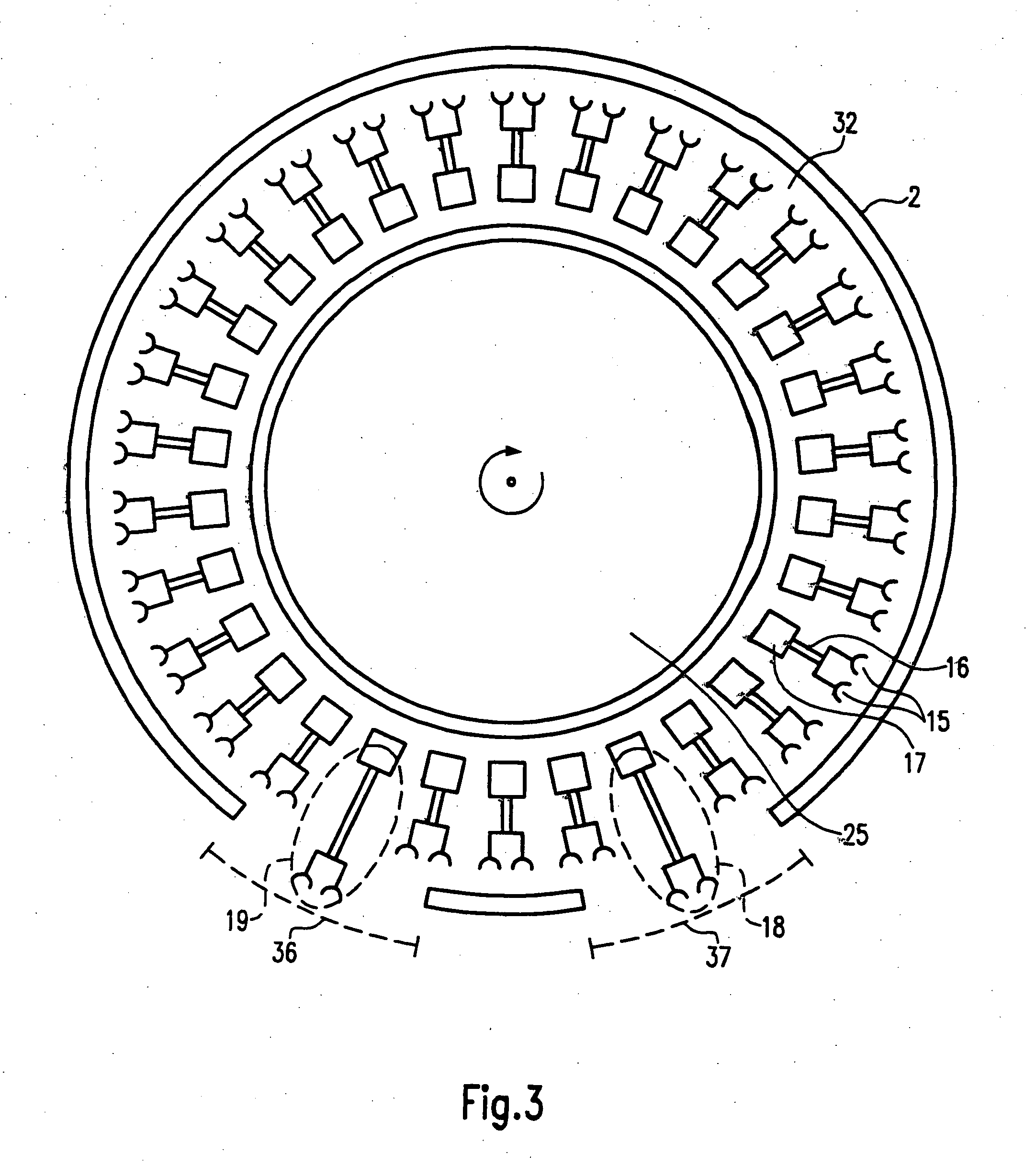
[0011] In an especially advantageous embodiment, only one plasma treatment area is provided, that area taking the form of a ring or a ring segment through which the containers can be guided. This allows a simple design for conveyance of the containers because the containers can then be guided through the plasma treatment area, which is in the form of a ring segment, with the bottles suspended from a rotor, for example, and this increases the efficiency in comparison with a process using individual chambers or double chambers for treatment of the containers.
[0013] An embodiment in which the containers can be varied in height is also preferred. This makes it possible to place the containers in a treatment position. In particular in the case when an electrode, a microwave conductor or a tube for supplying a process gas is to be arranged in the container, the container with the opening situated upward may be shifted upward or downward to such an extent that the electrode, the microwave conductor or the tube is at least partially inside the container. The situation is similar with a horizontal movement of a horizontal bottle or with an arrangement in which the bottle is situated with the opening upward so that it is inverted over the material or the electrode with a downward movement.
[0017] In addition, airlocks which have specially designed cells are also advantageous. These cells can accommodate several bottles at the same time and thus allow a higher bottle throughput with a simplified design.

Problems solved by technology

Disadvantages here include the great mechanical complexity and the inaccurate distribution of the coating on the irregularly shaped bottle bodies.

Method used


Image

  • Device and Process for Plasma Coating/Sterilization
  • Device and Process for Plasma Coating/Sterilization
  • Device and Process for Plasma Coating/Sterilization

Examples


Embodiment Construction

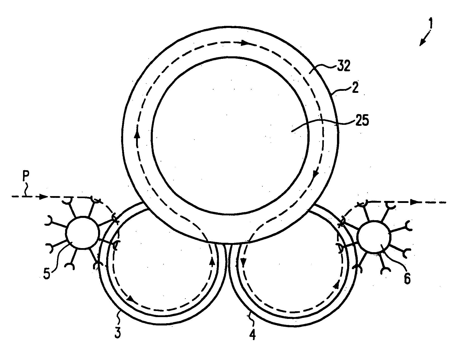
[0027]FIG. 1 shows a top view of a device 1 for treating containers. The path provided for the containers is indicated by the dotted line P. From a feed conveyor (not shown), the containers are transferred by a transfer star 5 to an input airlock chamber 3, from which the containers may go to the treatment chamber 2 to be discharged through the airlock 4 after a passage through the treatment chamber and be transferred by transfer star 4 [sic; 6] to a discharge conveyor (not shown).

[0028] The treatment chamber 2 has a plasma treatment area 32 in which the containers are able to revolve. A hollow body 25 is arranged in the treatment chamber 2. This yields a ring-shaped plasma treatment area 32. The hollow body 25 advantageously reduces the volume of the plasma treatment area 32 to be evacuated. The greater the size of the hollow body, the smaller the space of the plasma treatment area 2. The airlocks 3 and 4 and the treatment chambers 2 have rotating conveyor means with which the con...


PUM

PropertyMeasurementUnit
Fractionaaaaaaaaaa
Fractionaaaaaaaaaa
Fractionaaaaaaaaaa

Abstract

A device for treating containers such as bottles, preferably PET containers, such as PET bottles, with a plasma, whereby the device is designed for sterilizing and / or coating the containers. In addition, the device also relates to a method for treating containers, preferably PET containers such as PET bottles, with a plasma, whereby the treatment comprises sterilization and / or the coating of the containers. Also provided is an airlock for containers such as bottles, in particular PET containers such as PET bottles, having cells to receive the containers, at least one cell being designed to receive at least two containers.

Description

CROSS-REFERENCE TO RELATED APPLICATION [0001] This is the U.S. national stage under 35 U.S.C. §371, of international application no. PCT / EP2005 / 007773, having an international filing date of Jul. 16, 2005, and claims priority to German application no. 10 2004 036 063.4 filed on Jul. 24, 2004.FIELD OF THE DISCLOSURE [0002] The disclosure relates to a device and a method for treating containers, especially PET containers such as PET bottles, with a plasma. BACKGROUND OF THE DISCLOSURE [0003] DE 698 15 359 T2 describes a method in which plastic containers can be provided with a gas barrier layer on the outside. To do so, a coating material is vaporized and the plastic containers are guided in various orientations over the vaporization source. [0004] Disadvantages here include the great mechanical complexity and the inaccurate distribution of the coating on the irregularly shaped bottle bodies. [0005] Such gas barrier layers serve to delay the volatilization of CO2 from beverages, for e...

Claims


Application Information

Patent Timeline
IPC IPC(8): A61L2/14B05D3/06B65B55/08H01H37/32H01J37/32
CPCA61L2/14
Inventor ZIMMERER, JOHANNHUMELE, HEINZ
Owner KRONES AG
Learn More