Drive System, Power Output System Incorporating The Drive System, A Vehicle Equipped With The Power Output System, And Control Method For A Drive System

a technology of power output system and drive system, which is applied in the direction of engine-driven generators, instruments, transportation and packaging, etc., can solve the problems of difficult to determine whether the drive system is operating steadily using the torque output from the motor, and difficult to determine whether the drive system is operating steadily using the torque, etc., to achieve the effect of appropriately determining whether the learning operation is performed, reducing the transmission ratio, and improving the learning operation

Inactive Publication Date: 2008-02-07
TOYOTA JIDOSHA KK +1
View PDF12 Cites 20 Cited by
  • Summary
  • Abstract
  • Description
  • Claims
  • Application Information

AI Technical Summary

Benefits of technology

[0007] With the drive system according to the invention, at least one of the operational state of the actuator and the operational state of the motor is learned, when the transmission ratio of the shifting/transmitting means is changed such that the amount of change in the driving force on the drive shaft side, that is output to the drive shaft from the motor via the shifting/transmitting means, is within the predetermined range. Also, the actuator of the shifting/transmitting means is controlled using the results of the learning operation such that the transmission ratio of the shifting/transmitting means changes. Because at least one of the operational state of the actuator and the operational state of the motor is learned when the transmission ratio of the shifting/transmitting means is changed such that the amount of change in the driving force on the drive shaft side is the predetermined range, and the actuator is controlled using those results of the learning operation, it is possible to more appropriately determine whether the learning operation can be performed. In addition, it is possible to correct any deviations that may have occurred due to changes over time in the transmission, and more appropriately change the transmission ratio of the shifting/transmitting means. As a result, the learning operation can be performed more appropriately.
[0008] In the drive system according to the invention, the shift learning means may also be configured to estimate the driving force on the drive shaft side based on driving of the motor, and perform the learning operation when the transmission ratio of the shifting/transmitting means is changed such that the amount of change in the estimated driving force on the drive shaft side is within the predetermined range. In this case, the shift learning means may also be configured to estimate the driving force on the drive shaft side using one of a current value applied to the motor and a torque command value of the motor. As a result, the driving force on the drive shaft side can be more accurately estim...

Problems solved by technology

However, it is difficult to determine whether the drive system is operating steadily using the torque that is output from the motor, for example, when the shift speed of the transmission is changed while maintaining power output from the motor, because the torque that is output from the motor changes when the shift speed changes.
Furthermore, in a power output device that outputs bot...

Method used


Image

  • Drive System, Power Output System Incorporating The Drive System, A Vehicle Equipped With The Power Output System, And Control Method For A Drive System
  • Drive System, Power Output System Incorporating The Drive System, A Vehicle Equipped With The Power Output System, And Control Method For A Drive System
  • Drive System, Power Output System Incorporating The Drive System, A Vehicle Equipped With The Power Output System, And Control Method For A Drive System

Examples


Embodiment Construction

[0030] Next, example embodiments of the invention will be described.

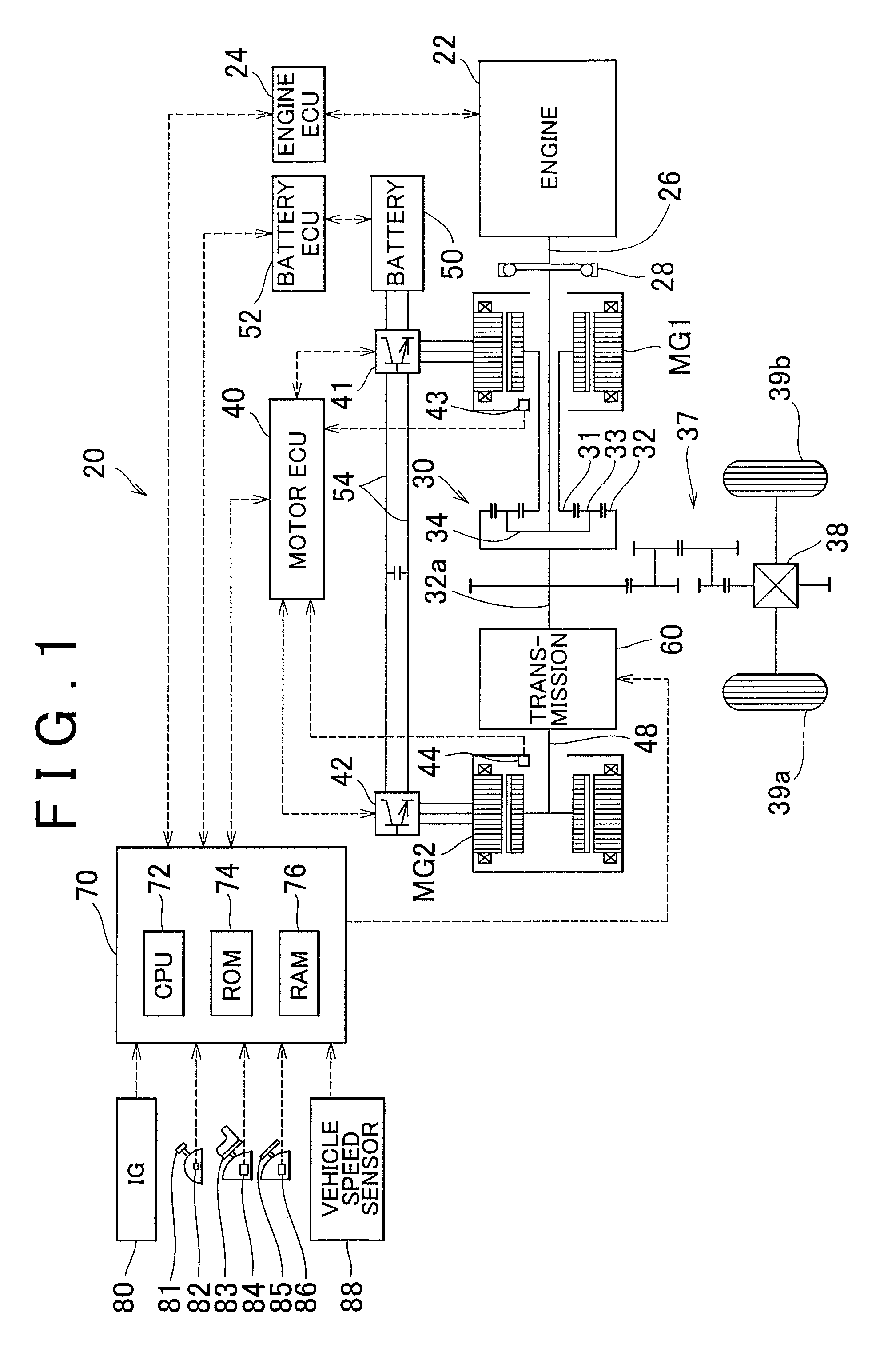
[0031]FIG. 1 is the block diagram schematically showing the configuration of a hybrid vehicle 20 equipped with a power output system as one example embodiment of the invention. As shown in the drawing, the hybrid vehicle 20 includes an engine 22, a three-shaft type power split / integration mechanism 30 that is connected via a damper 28 to a crankshaft 26 that serves as an output shaft of the engine 22, a motor MG1 that generates power and that is connected to the power split / integration mechanism 30, a motor MG2 that is connected to the power split / integration mechanism 30 via a transmission 60, and a hybrid electronic control unit (hereinafter, referred to as a “hybrid ECU”) 70 that controls the overall vehicle.

[0032] The engine 22 is an internal combustion engine that outputs power by burning a hydrocarbon fuel such as gasoline or light oil. An engine electronic control unit (hereinafter simply referred to as “en...


PUM


Abstract

In a drive system, where power from a motor is transmitted to a drive shaft and a transmission ratio is changed by a transmission, if the absolute value of the difference between the reference torque Tm2r0, which is the drive shaft side torque Tm2r at the onset of a change in the shift speed of the transmission, and the driving shaft side torque Tm2r during the change is less than the threshold value α until the end of the change (S280), the application state of a brake in the transmission during the change and the state of the hydraulic pressure supplied to the brake are learned (S290). During the change, and actuator of the transmission is controlled using those learned results. Accordingly, any deviations that may have occurred due to changes over time in the transmission, etc. are corrected and the shift speed of the transmission is changed more appropriately.

Description

FIELD OF THE INVENTION [0001] The invention relates to a drive system and a power output system that incorporates the drive system, a vehicle equipped with the power output system, and a method for controlling such drive system. BACKGROUND OF THE INVENTION [0002] Japanese Patent Application Publication No. JP-A-2002-225578 describes a drive system incorporated in a vehicle where power is output from a motor to a drive shaft, which is connected to an axle, via a transmission. The system makes the power from the motor appropriate for the vehicle speed by changing the shift speed of the transmission in accordance with the vehicle speed, and then outputs that power to the drive shaft. [0003] With this kind of drive system, in order to correct any deviations that may have occurred due to changes over time in the transmission and more appropriately change the transmission ratio of the transmission, it is desirable to perform a learning operation and control an actuator of the transmission...

Claims


Application Information

Patent Timeline
IPC IPC(8): F16H61/00B60W10/10B60K6/44B60K6/445B60K6/448B60K6/52B60K6/54B60L50/16B60W10/02B60W10/08B60W20/00F16H59/14F16H59/70F16H61/02F16H61/68F16H61/684F16H61/686F16H63/50
CPCB60K6/445B60L2240/486B60W10/08B60W10/10B60W20/00B60W2710/105Y10T477/78F16H2061/0087F16H2342/04Y02T10/6239Y10T477/75Y10T477/638F16H61/0437B60L7/26B60L15/2009B60L15/2054B60L2240/12B60L2240/421B60L2240/423B60L2240/441B60L2240/443B60L2250/26Y02T10/72Y02T10/62Y02T10/64B60W20/30B60W10/026
Inventor KAMICHI, KENSUKEUEOKA, KIYOSHIROYAMAMOTO, MASAYAOKASAKA, KAZUOMITAJIMA, YOICHI
Owner TOYOTA JIDOSHA KK
Why Eureka
Try Eureka