Collision avoidance of a mobile unit

a mobile unit and collision avoidance technology, applied in the field of collision avoidance system, program and method of mobile units, can solve the problem that conventional techniques have not presented the technique for detecting the direction in which an obstacle is approaching, and achieve the effect of avoiding collision and avoiding collision

Inactive Publication Date: 2008-02-07
HONDA MOTOR CO LTD
View PDF5 Cites 37 Cited by
  • Summary
  • Abstract
  • Description
  • Claims
  • Application Information

AI Technical Summary

Benefits of technology

[0014] In addition, the present invention provides a computer program for avoiding collision with an obstacle that approaches a mobile unit. This program causes a computer to perform capturing an image of an environment surrounding the mobile unit, calculating motion vectors on the image based on the image captured by the image capturing function, a function of calculating collision probabilities of the obstacle based on the motion vectors in a plurality of pixels in the image, and comparing the collision probabilities in the plurality of pixels to determine a direction in which the obstacle approaches the mobile unit. The mobile unit is moved in a direction different from the determined direction.
[0015] Further, the present invention provides a method for avoiding collision with an obstacle that approaches a mobile unit. This method includes the steps of capturing an image of an environment surrounding the mobile unit, calculating motion vectors on the image based on the image captured by the image capturing step, calculating collision probabilities of the obstacle based on the motion vectors in a plurality of pixels in the image, and comparing the collision probabilities on the plurality of pixels to determine a direction in which the obstacle approaches the mobile unit. The mobile unit is moved in a direction different from the determined direction.

Problems solved by technology

However, a technique for detecting a direction in which an obstacle is approaching has not been presented by conventional techniques such as in the above documents.

Method used


Image

  • Collision avoidance of a mobile unit
  • Collision avoidance of a mobile unit
  • Collision avoidance of a mobile unit

Examples


Embodiment Construction

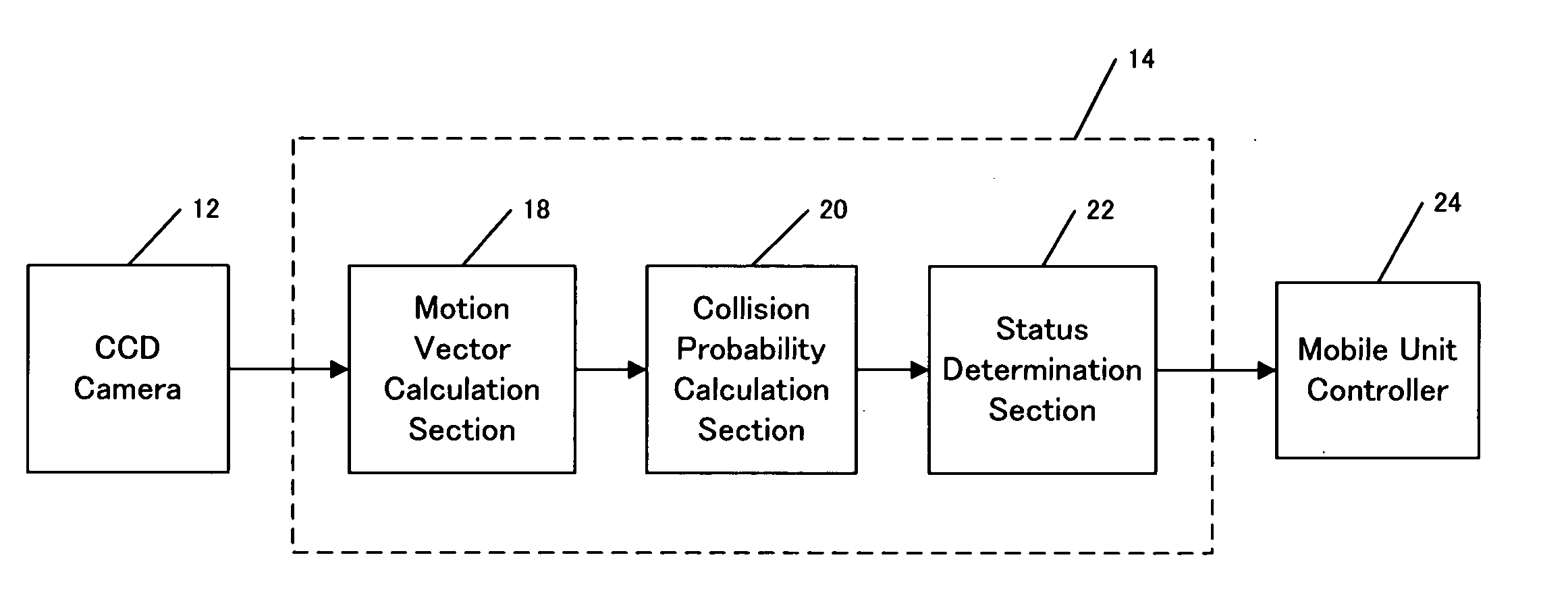
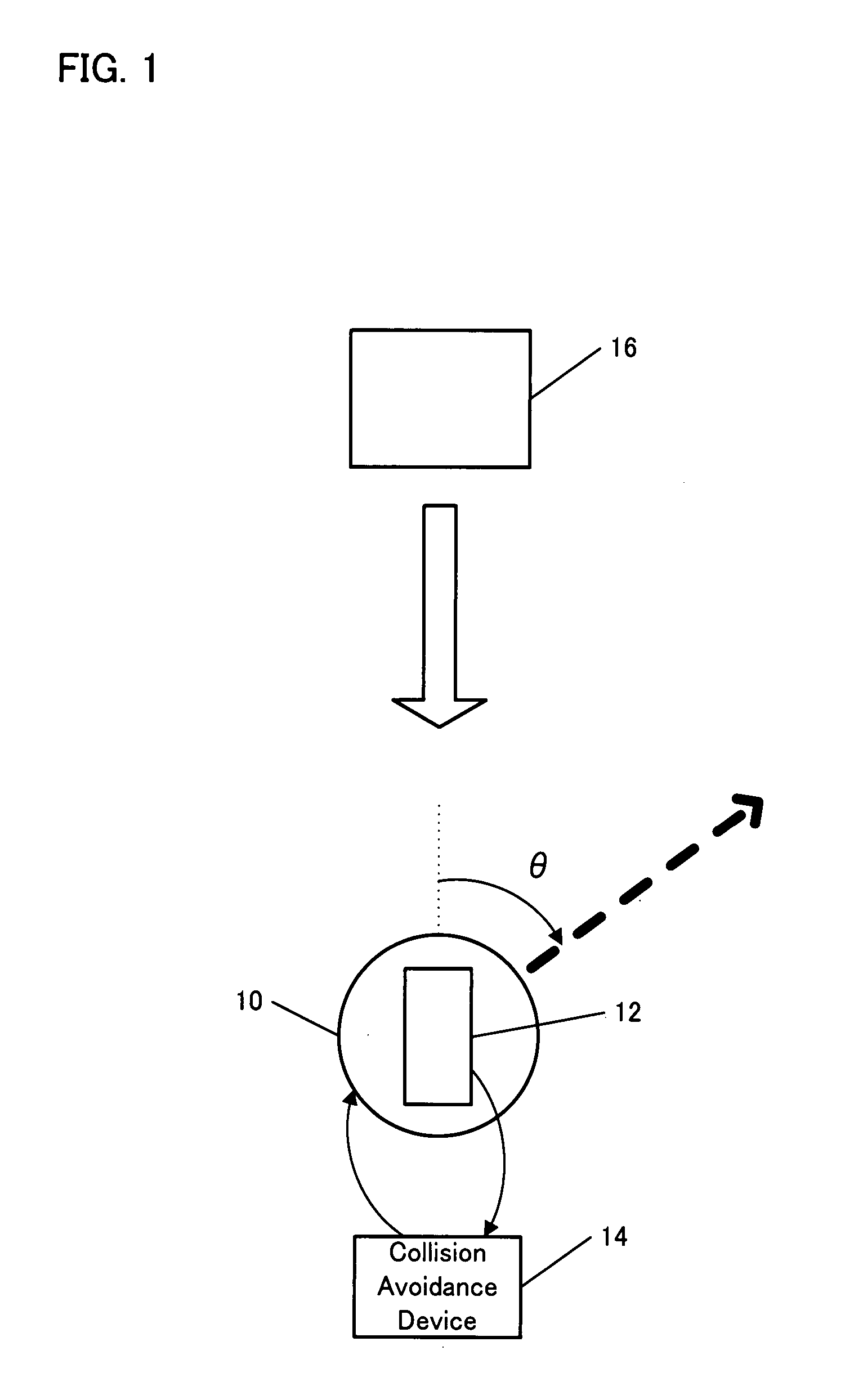
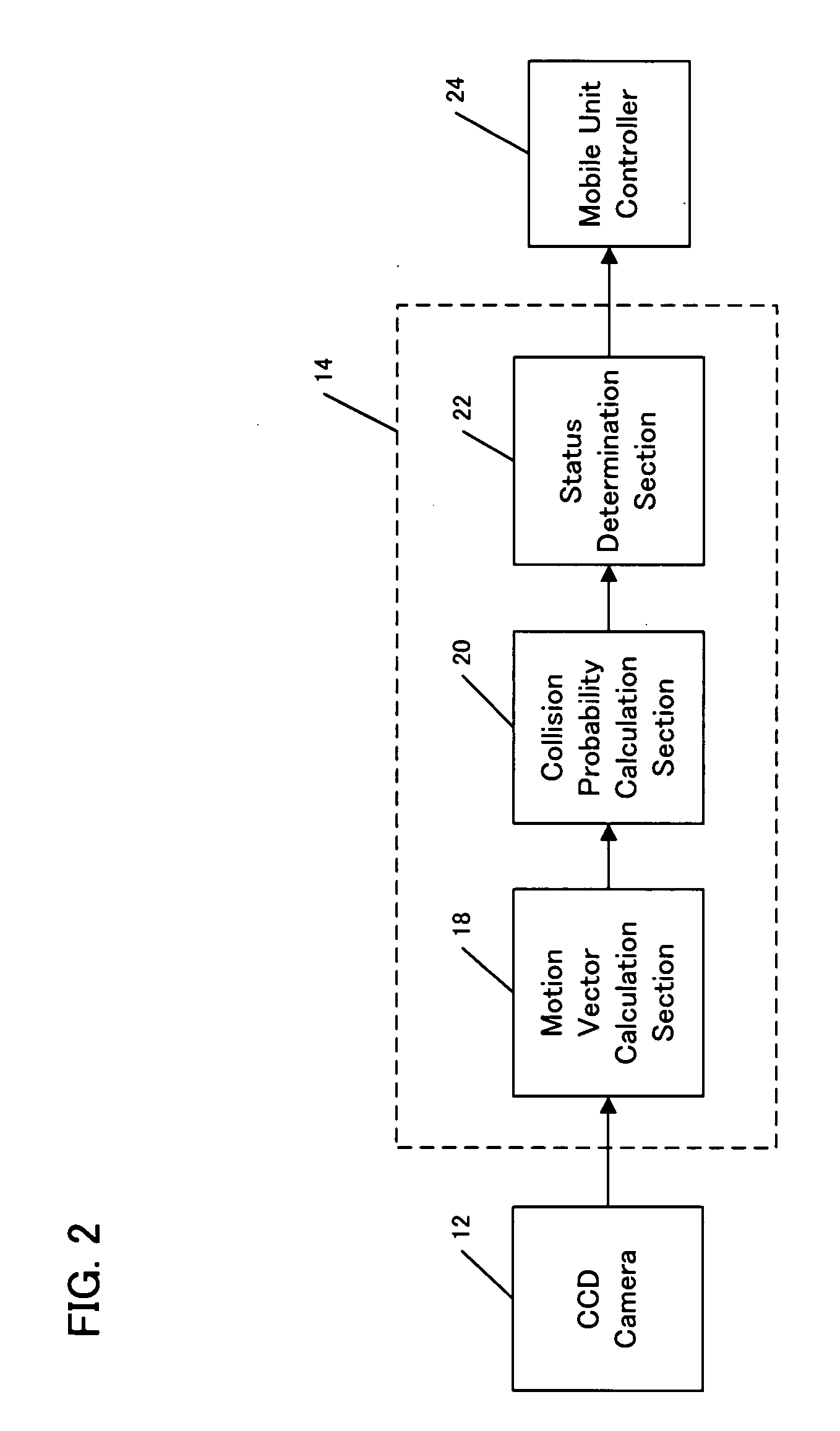
[0024] Embodiments of the present invention will be described with reference to the drawings. FIG. 1 is a schematic diagram which illustrates a collision avoidance system of a mobile unit 10 according to one embodiment of the present invention.

[0025] In the present embodiment, the mobile unit 10 is a small autonomous mobile robot with two wheels, for example, Khepera Robot™ which is highly versatile and widely used as a small mobile robot for experiment. The mobile unit 10 is provided with image capturing means such as a CCD camera 12 on the main body, and recognizes an obstacle 16 around the mobile unit 10 based on an image captured by the CCD camera 12. The image captured by the CCD camera 12 is transmitted to a collision avoidance device 14 connected via a wired or wireless connection to the mobile unit 10.

[0026] The collision avoidance device 14 analyzes the image received from the mobile unit 10 to determine a direction in which the obstacle 16 is approaching the mobile unit ...


PUM


Abstract

A collision avoidance system for a mobile unit includes an image capturing unit for capturing an image of an environment surrounding a mobile unit. Motion vector is calculated based on the captured image. Collision probability is calculated based on the motion vectors of the image. The system includes a plurality of receptive field units that are modeled on the optic lobe cells of the flies. Each of the receptive field units includes a filter producing an excitatory response to the motion vector diverging from the center of the receptive field in the central area of the receptive field and producing an inhibitory response to the motion vector converging toward the center of the receptive field in the areas around the central area. The outputs of the receptive field units are compared to determine a direction in which the obstacle approaches the mobile unit. The mobile unit moves in a direction to avoid collision.

Description

BACKGROUND OF THE INVENTION [0001] 1. Field of the Invention [0002] The present invention relates to a collision avoidance system, program, and method of a mobile unit for avoiding collision with an obstacle, and more particularly, to a collision avoidance system, program, and method of a mobile unit which estimates a collision probability and an approaching direction of an obstacle using a plurality of motion detectors which are modeled on the optic lobe neurons of flies. [0003] 2. Description of the Related Art [0004] Collision avoidance against an obstacle is a function necessary for a mobile unit to arrive at a destination safely. Many techniques for avoiding collision with an obstacle have been proposed, which are based on optical flows extracted from visual information such as camera image. [0005] For example, Japanese Patent Application Publication No. 11-134504 discloses a device which detects collision with an obstacle based on a value obtained by subtracting a vector sum o...

Claims


Application Information

Patent Timeline
Patent Type & Authority Applications(United States)
IPC IPC(8): G08G1/16
CPCG06K9/4619G06K9/00805G08G1/16G08G1/165G08G1/166G06V20/58G06V10/449
Inventor HASEGAWA, YUJIOKUMA, JIRO
Owner HONDA MOTOR CO LTD
Why Eureka
Try Eureka