
Audio Waveform Processing Device, Method, And Program

a processing device and audio waveform technology, applied in the field of audio waveform processing, can solve the problems of inability to achieve high quality pitch shifting, time stretching and discomfort in the auditory, etc., and achieve the effect of reducing the price of the audio waveform synthesizer device, high quality and high quality

Active Publication Date: 2008-02-07
P SOFTHOUSE
View PDF30 Cites 9 Cited by
  • Summary
  • Abstract
  • Description
  • Claims
  • Application Information

AI Technical Summary

Benefits of technology

[0027] According to the invention set forth in claims 1 and 3, the frequency analysis and the synthesis process of the audio signal are performed as to each of the bands divided into multiple frequency bands to evaluate the similarity between the original waveform and the waveform after the synthesis process as to each band. The cross-fade process is performed at the locations of high similarity between the waveform after the synthesis process and the band original waveform so that the phase change occurring on the waveform synthesis can be reset. Thus, it is possible to obtain the audio output of high quality which does not cause auditory sense of discomfort.
[0028] According to the invention set forth in claims 2 and 4, the similarity between the original waveform and the waveform after the synthesis process is evaluated by regarding the audio waveform as-is as one band without performing the band division. The cross-fade process is performed at the locations of high similarity between the waveform after the synthesis process and the original waveform so that the phase change occurring on the waveform synthesis can be reset. Thus, it is possible to realize the audio output of high quality which does not cause auditory sense of discomfort with a smaller number of parts so as to realize a lower price of an audio waveform synthesizing device.
[0029] According to the invention set forth in claim 5, the audio waveform processing method described in one of claims 3 and 4 can be performed by a commercially available audio processing program for a personal computer so that vocoder-method audio processing of high quality can be realized at even lower prices.
[0030] According to the invention set forth in claims 6 and 8, the frequency analysis and the synthesis process are performed as to each of the bands of the audio signal divided into multiple frequency bands. The phase condition after the synthesis process of each band is compared with the phase condition of the original waveform to generate the waveform which is highly correlated with the phase condition after the synthesis process and is a linear phase lead or a linear phase lag of the original waveform as a phase synchronization waveform. The cross-fade process is performed to turn the waveform after the synthesis process to a movement synchronization waveform so that the phase change occurring on the waveform synthesis can be reset. Thus, it is possible to obtain the audio output of high quality which does not cause auditory sense of discomfort.
[0031] According to the invention set forth in claims 7 and 9, the audio waveform is processed by regarding it as-is as one band without performing the band division in the frequency band division of the device according to claim 6. Thus, it is possible to realize the audio output of high quality which does not cause auditory sense of discomfort with a smaller number of parts so as to realize lower prices of an audio waveform synthesizing device.
[0032] According to the invention set forth in claim 10, the audio waveform processing method described in one of claims 8 and 9 can be performed by a commercially available audio processing program for a personal computer so that vocoder-method audio processing of high quality can be realized at even lower prices.

Problems solved by technology

For this reason, there arises an auditory sense of discomfort due to, for example, mutual cancellation of sounds or a lack of feeling of normalcy of a stereo sound.
Therefore, the time stretching and the pitch shifting of high quality cannot be realized.

Method used


Image

  • Audio Waveform Processing Device, Method, And Program
  • Audio Waveform Processing Device, Method, And Program
  • Audio Waveform Processing Device, Method, And Program

Examples


first embodiment

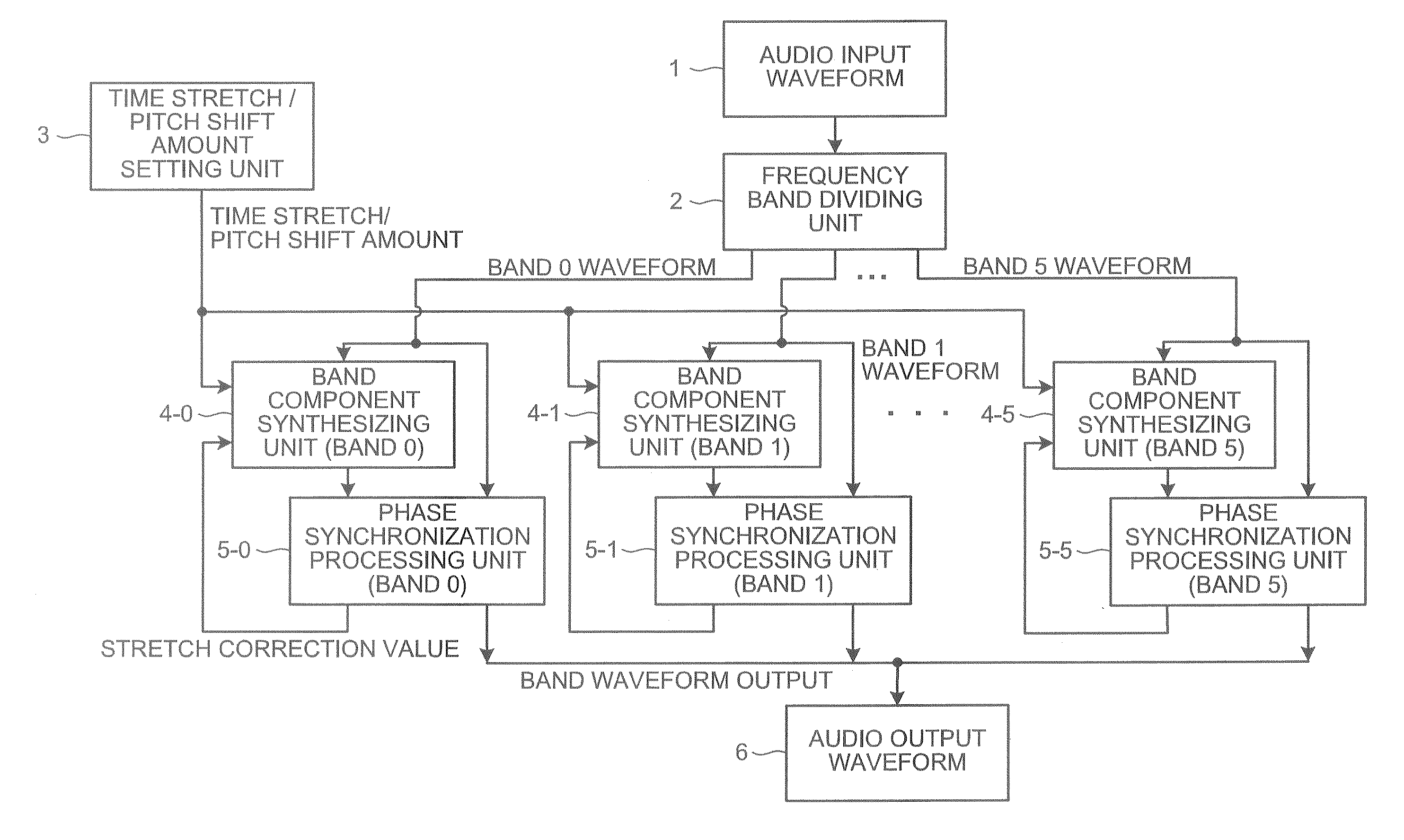
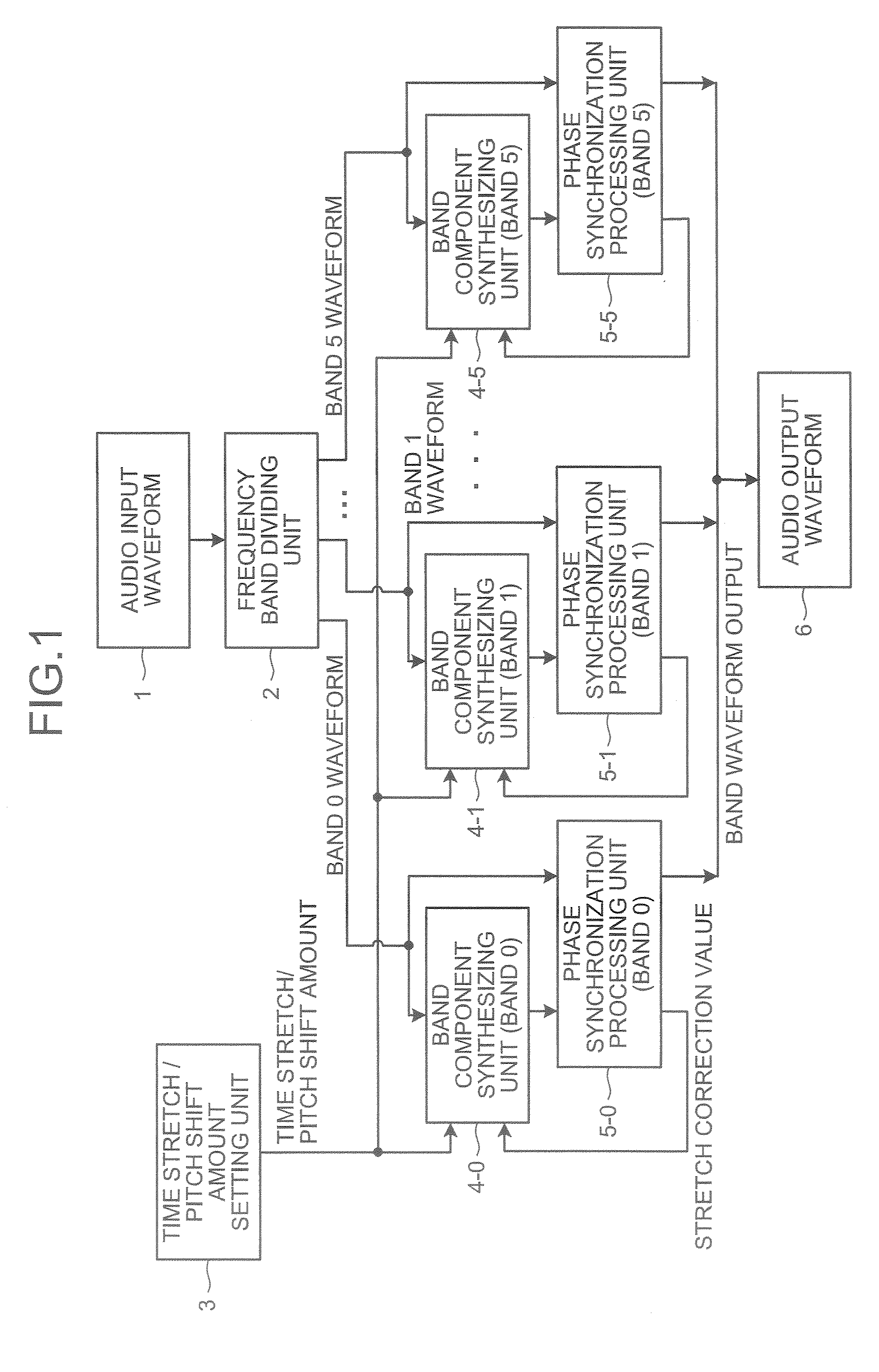
[0110]FIG. 1 shows a block diagram of audio waveform processing according to claims 1 and 3, which is a first embodiment of the present invention. Audio waveforms handled in this embodiment are digitized.

[0111] An audio input waveform 1 is divided into several bands by a frequency band dividing unit 2. This embodiment divides it into six bands. Reference numeral 3 denotes a time stretch / pitch shift amount setting unit, where a parameter is changed by an operation by a user. Band waveforms generated by the frequency band dividing unit 2 undergo a frequency analysis by band component synthesizing units 4-0 to 4-5, and the waveforms are synthesized according to a time stretch / pitch shift amount set based on a result of the frequency analysis while time expansion / compression and pitch conversion are performed.

[0112] Next, phase synchronization processing units 5-0 to 5-5 perform phase synchronization processing by using the waveforms synthesized by the band component synthesizing unit...

second embodiment

[0140] The first embodiment has described the example of implementing the waveform processing by performing the band division on the audio input waveform. It is possible, however, to implement the same waveform processing as that described in the first embodiment by using the means disclosed in claims 2 and 4 which do not perform the band division on the audio input waveform. In FIG. 1, the frequency band dividing unit 2, the band component synthesizing unit (band 1) 4-1 to the band component synthesizing unit (band 5) 4-5, and the phase synchronization processing unit (band 1), 5-1 to the phase synchronization processing unit (band 5) 5-5 are deleted, and the audio input waveform 1 is directly inputted to the band component synthesizing unit (band 0) 4-0 and perform the same waveform processing as that described in the first embodiment.

third embodiment

[0141] Next, a computer program of claim 5 as a third embodiment will be described. FIG. 20 shows a flowchart of the computer program. First, input waveform data is read (step S1), and a frequency band dividing process (step S2) which is the same as the frequency band dividing unit 2 of FIG. 1 is performed so as to output the waveform of each band. This process is composed of an instruction group such as multiplications and additions for realizing the band-pass filter or an instruction group for executing FFT in the case of realizing the band division by Fourier transform.

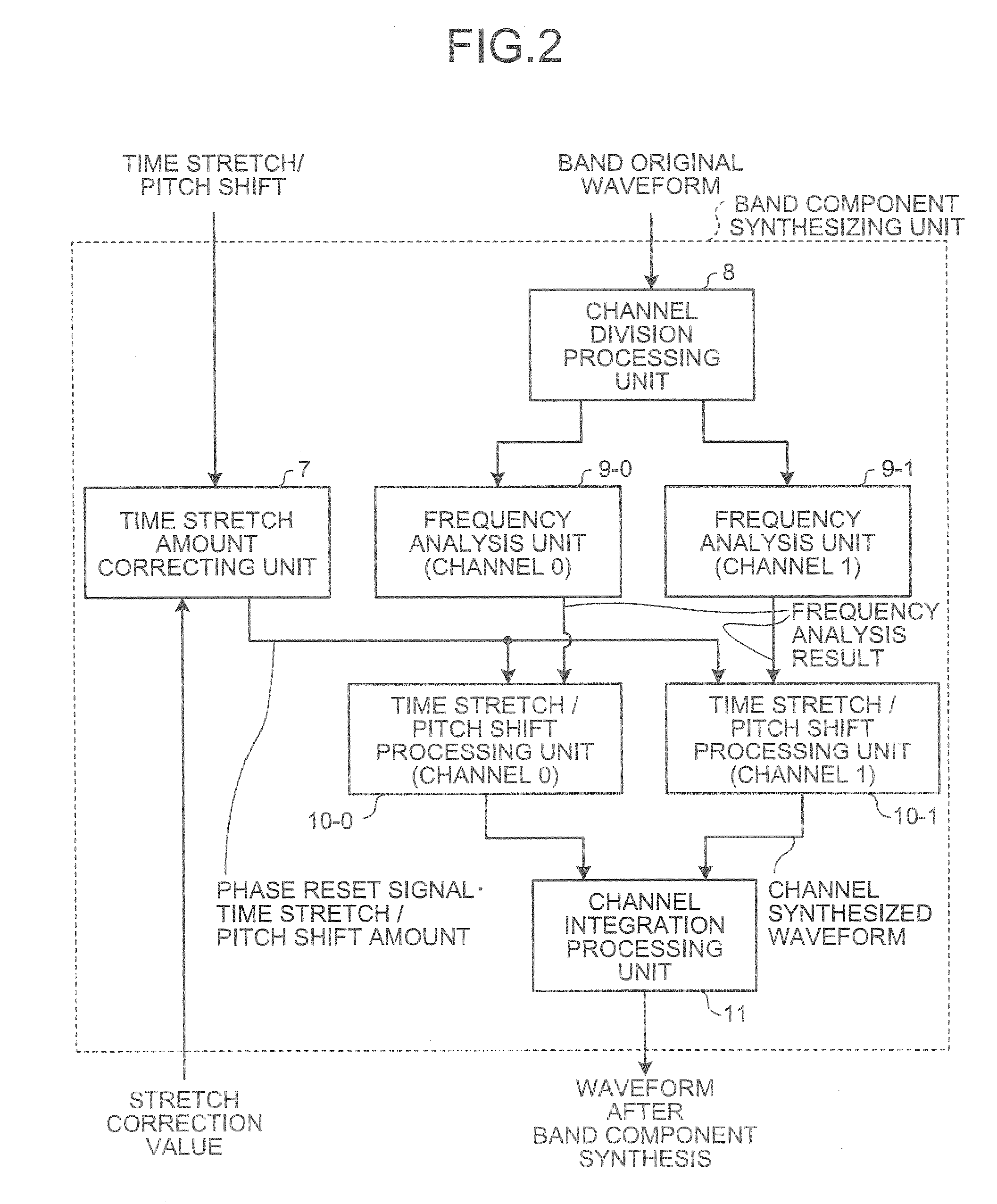
[0142] Next, an analytical process is performed as to instantaneous amplitude, angular frequency, and phases of band waveform data having undergone the frequency band division (step S3). This process is a part equivalent to the frequency analysis units 9-0 to 9-1 of FIG. 2, and is composed of the instruction group for executing the FET and instruction groups of square roots for calculating the amplitude, arctans f...


PUM


Abstract

An audio waveform processing not imparting any feeling of strangeness and high in definition, in which time stretch and pitch shift are performed by a vocoder method, and the variation of phase over the whole waveform caused by the vocoder method at all times is reduced. An audio input waveform is handled as one band as it is or subjected to frequency band division into bands. While performing time stretch and pitch shift of each band waveform like conventional vocoder methods, the waveforms are combined. The combined waveform of the band is phase-synchronized at regular intervals to reduce the variation of phase. The phase-synchronized waveforms of the band are added, thus obtaining the final output waveform.

Description

TECHNICAL FIELD [0001] The present invention relates to audio waveform processing for performing time stretching and pitch shifting by a vocoder method. BACKGROUND ART [0002] Time stretching is a process of expanding and compressing only a time axis of an audio waveform without changing a pitch thereof. Pitch shifting is a process of changing only the pitch without changing the time axis. There is a so-called vocoder method as a heretofore known audio waveform processing for performing the time stretching and the pitch shifting (refer to Patent Document 1 for instance). This method analyzes a frequency of an inputted audio waveform, compresses or expands the time axis on the time stretching, and scales the frequency of an outputted waveform and then adds each frequency component on the pitch shifting. [0003] In the case of a conventional vocoder methods there is a great change in a phase between an audio input waveform and a time-stretched and / or pitch-shifted waveform. FIGS. 7A and...

Claims


Application Information

Patent Timeline
IPC IPC(8): G10L13/00G10L19/02G10L13/06G10L13/07G10L21/003G10L21/043G10L21/049G10L25/18
CPCG10L21/04G10L19/0204G10L21/013G10L19/02G11B20/10
Inventor KUDOH, TAKUMA
Owner P SOFTHOUSE
Learn More