Failure diagnosis method for reducing agent addition valve

Inactive Publication Date: 2008-02-14
TOYOTA JIDOSHA KK +1
View PDF0 Cites 7 Cited by
  • Summary
  • Abstract
  • Description
  • Claims
  • Application Information

AI Technical Summary

Benefits of technology

[0020] When the aforementioned prescribed quantity difference is large, there is a possibility that the magnitude of error contained in the estimated post injection quantity and the magnitude of error contained in the estimated addition quantity are different from each other. In view o

Problems solved by technology

For this reason, it is not easy to improve the accuracy of fa

Method used


Image

  • Failure diagnosis method for reducing agent addition valve
  • Failure diagnosis method for reducing agent addition valve
  • Failure diagnosis method for reducing agent addition valve

Examples


Example

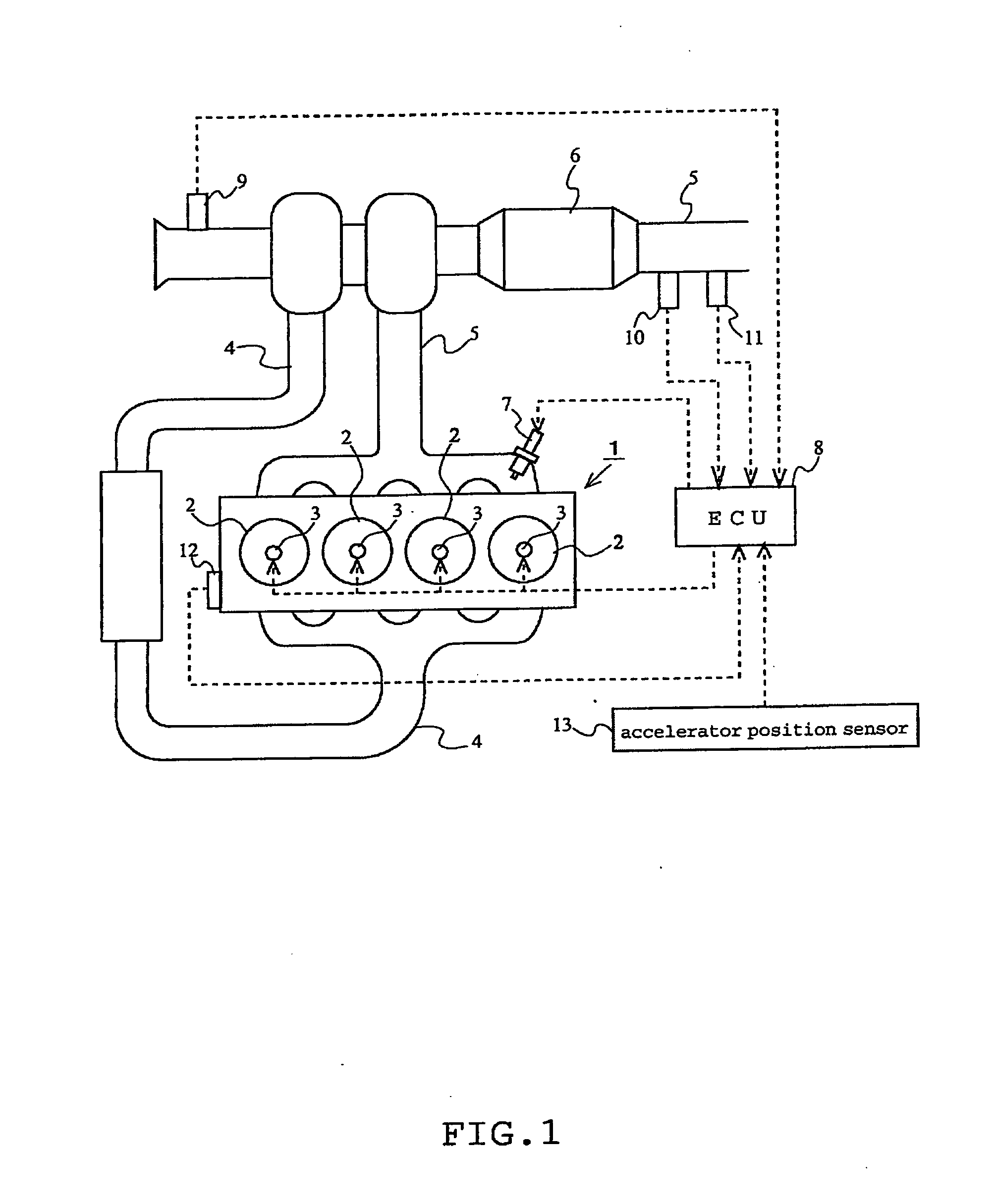
[0051] A first embodiment of the present invention will be described with reference to FIGS. 1 to 3. FIG. 1 schematically shows the general structure of an internal combustion engine to which the present invention is applied. The internal combustion engine 1 shown in FIG. 1 is a compression ignition type internal combustion engine (diesel engine) having four cylinders 2.

[0052] The internal combustion engine 1 is provided with a fuel injection valves 3 that can inject fuel directly into the respective cylinders 2 and an intake passage 4 for introducing air to the cylinders 2. The mixture of air introduced into each cylinder 2 from the intake passage 4 and fuel injected through the fuel injection valve 3 is ignited and burned.

[0053] The gas burned in each cylinder 2 (burned gas) is discharged to an exhaust passage 5. The exhaust gas discharged to the exhaust passage 5 is purified by an exhaust gas purification catalyst 6 provided at some midpoint in the exhaust passage 5 and then em...

Example

Second Embodiment

[0099] In the following a second embodiment of the present invention will be described with reference to FIG. 4. Here, features that are not found in the above described first embodiment will be described, and features the same as those in the first embodiment will not be further described.

[0100] In this embodiment described in the following, the estimated post injection quantity Qpst and the estimated addition quantity Qad obtained in the failure diagnosis according to the first embodiment described above are used to correct the prescribed addition quantity Qads in the subsequent processing.

[0101]FIG. 4 is a flow chart of an addition quantity correction routine for correcting the prescribed addition quantity Qads.

[0102] In the addition quantity correction routine, first in step S201, the ECU8 determines whether or not the above-descried failure diagnosis routine shown in FIG. 3 has already been executed. In other words, a determination is made as to whether or ...

Example

Third Embodiment

[0110] In the following, a third embodiment of the present invention will be described with reference to FIGS. 5 to 7. Here, features that are not found in the above described first embodiment will be described, and features the same as those in the first embodiment will not be further described.

[0111] In this embodiment described in the following, diagnosis of a failure of the air flow meter 9, the exhaust gas temperature sensor 10 and the A / F sensor 11 is performed on condition that it is determined in the failure diagnosis according to the above described first embodiment that the reducing agent addition valve 7 is working properly.

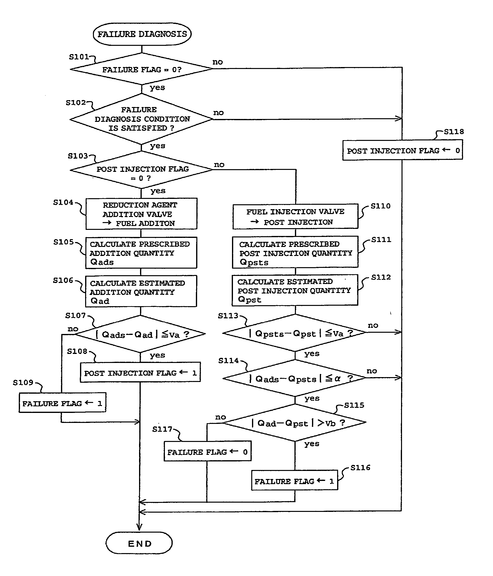
[0112]FIG. 5 is a flow chart of a sensor failure diagnosis routine for diagnosing a failure of the air flow meter 9, the exhaust gas temperature sensor 10 and the A / F sensor 11. In this sensor failure diagnosis routine, first in step S301, the ECU 8 determines whether or not the above described failure diagnosis routine shown in FIG....


PUM


Abstract

An object of the invention is to diagnose a failure of an addition valve provided in the exhaust system of an internal combustion engine. To achieve the object, post injection through a fuel injection valve of the internal combustion engine and reducing agent addition through the reducing agent addition valve are performed at different timings, the quantity of fuel injected through the fuel injection valve when the post injection is performed and the quantity of reducing agent added through the reducing agent addition valve when the reducing agent addition is performed are estimated based on a same parameter, and it is diagnosed that the reducing agent addition valve has a failure on condition that the difference between the estimated fuel quantity and the estimated reducing agent quantity exceeds a predetermined quantity.

Description

TECHNICAL FIELD [0001] The present invention relates to a technology of diagnosing a failure of a reducing agent addition valve provided in the exhaust system of an internal combustion engine. BACKGROUND ART [0002] In recent years, the exhaust system of some internal combustion engines is equipped with an addition valve for adding a reducing agent such as fuel into the exhaust gas. As a technique of diagnosing a failure of such an addition valve, there is a known method of diagnosing a failure of such a reducing agent addition valve in which the air-fuel ratio of the exhaust gas into which reducing agent has been added through the addition valve is detected and a failure of the addition valve is diagnosed by comparing the air-fuel ratio of the exhaust gas thus detected and a reference value (see, for example, Japanese Patent Application Laid-Open No. 2002-38928). [0003] Japanese Patent Application Laid-Open No. 2002-161733 discloses a diagnosis technique in which the quantity of red...

Claims


Application Information

Patent Timeline
IPC IPC(8): F01N3/00
CPCF01N3/0253F01N3/0814F01N3/0842F01N3/36F02D41/402F01N2550/05F01N2610/03Y02T10/47F02D41/221F01N11/00Y02T10/40
Inventor SHIBATA, DAISUKESAWADA, HIROSHIMAEDA, SATORU
Owner TOYOTA JIDOSHA KK
Why Eureka
Try Eureka