Stationary bedknife for disc chipper apparatus

a technology of disc chipper and bedknife, which is applied in the direction of cocoa, flat surfacing machine, solid separation, etc., can solve the problems of reducing the overall incidence of slivers, drastically affecting the throughput of the chipper, and adding to the overall complexity and cost. , to achieve the effect of reducing the overall footprint (i.e., size) of the chipper, facilitating removal and/or adjustment of the bedknife, and improving the overall cutting

a technology of disc chipper and bedknife, which is applied in the direction of cocoa, flat surfacing machine, solid separation, etc., can solve the problems of reducing the overall incidence of slivers, drastically affecting the throughput of the chipper, and adding to the overall complexity and cost. , to achieve the effect of reducing the overall footprint (i.e., size) of the chipper, facilitating removal and/or adjustment of the bedknife, and improving the overall cutting

US20080035242A1Active Publication Date: 2008-02-14CEM MACHINE

Image

  • Stationary bedknife for disc chipper apparatus
  • Stationary bedknife for disc chipper apparatus
  • Stationary bedknife for disc chipper apparatus

Examples


Embodiment Construction

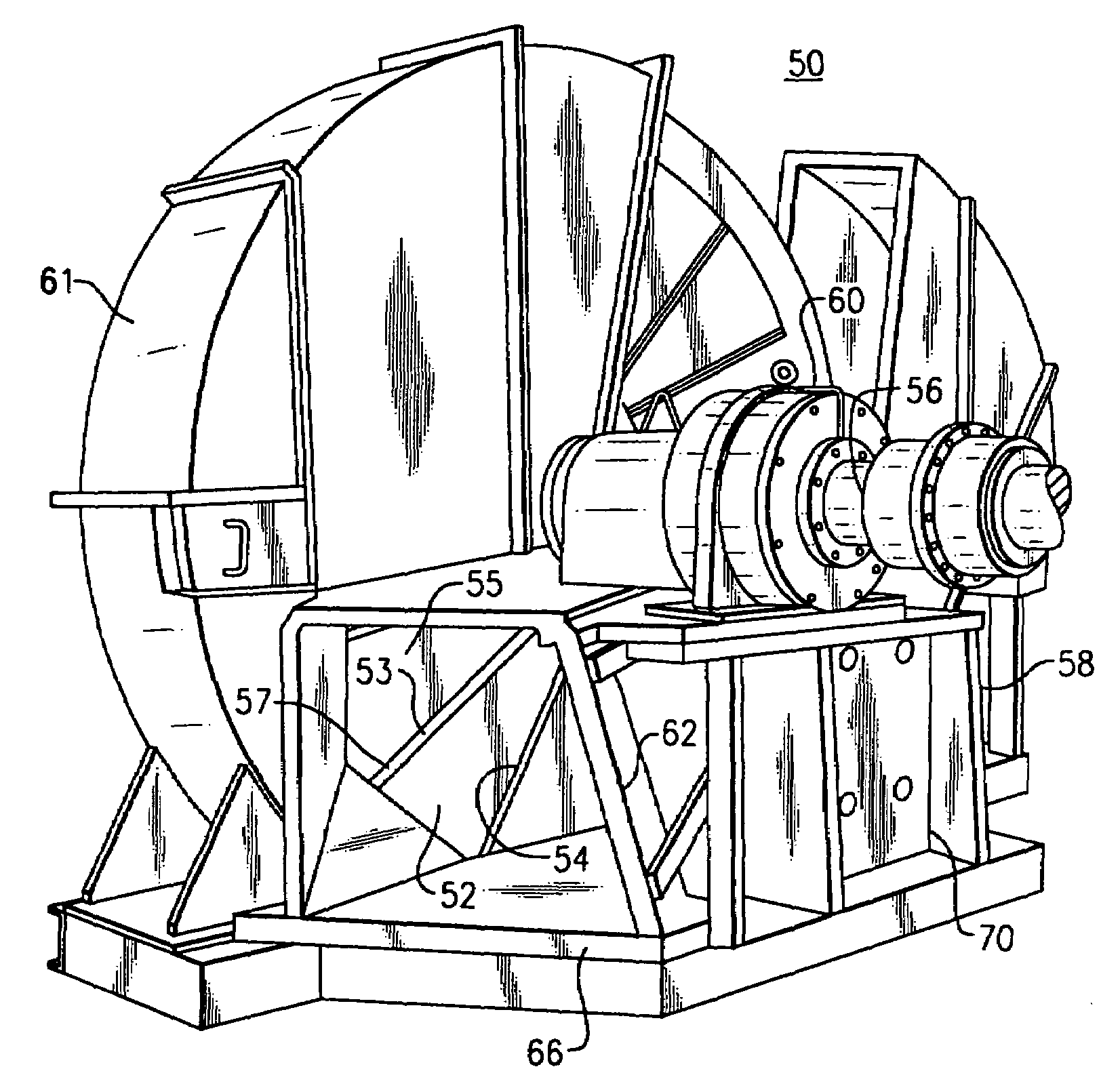
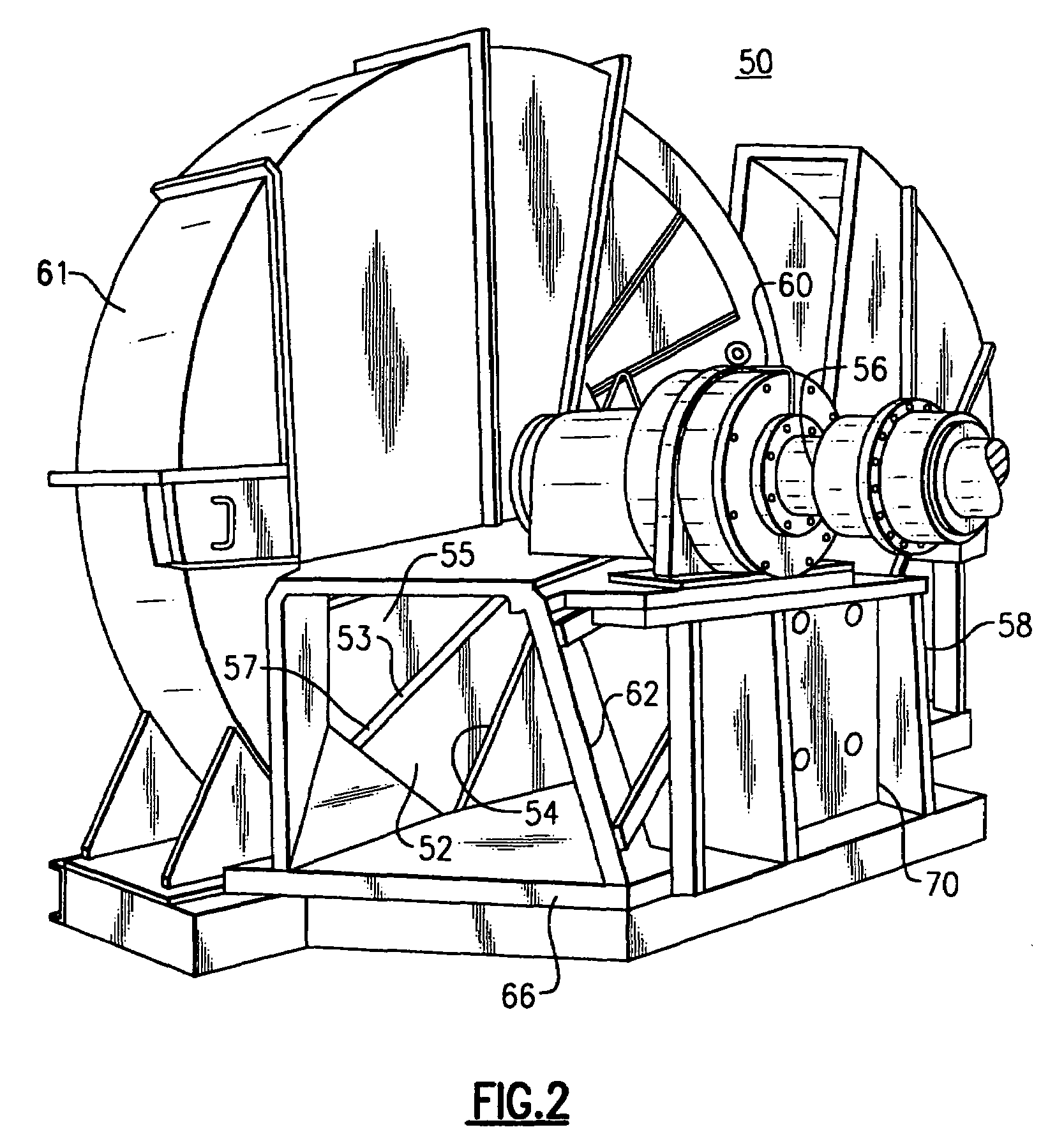
[0025]The following relates to an exemplary embodiment of a stationary bedknife as used in a rotary wood chipping apparatus, hereinafter referred to throughout as disc chippers or chippers. It will be readily apparent that other modifications and variations are possible within the inventive ambits discussed herein. For example, the following discussion relates to the inclusion of the exemplary bedknife in a horizontal disc chipper. However, it will become immediately clear that other apparatus, e.g., gravity feed disc chippers, could similarly be utilized. Moreover, the presently described bedknife relates to a vertical bedknife (e.g., the cutting edge is disposed in a substantially vertical orientation). However, the inventive concepts described herein are not intended to be limited to this geometry. In addition, certain terms are used through the course of discussion in order to provide a frame of reference with regard to the accompanying drawings. These terms should not be regard...


PUM


Abstract

A disc cutting apparatus for chipping wood chips from a log includes a chipper frame, a rotary cutting disc having a plurality of substantially radially disposed knife assemblies in relation to a proximal facing side of the disc and a feed spout into which a log is fed into the chipper apparatus. The apparatus further includes a bedknife, the bedknife having a first surface and an opposing second surface that is nonparallel to the first surface such that a wedge is produced between the first surface and the second surface for fitting within a corresponding nonparallel gap in the chipper frame. The bedknife further includes at least one secondary trimming edge for more complete reduction of wood chipped and for reducing the size of slivers formed.

Description

FIELD OF THE INVENTION[0001]The application relates to the field of rotary disc chipping apparatus for cutting substantially uniform chips from logs. In particular, this application is directed to an improved bedknife for use in a rotary disc chipper.BACKGROUND OF THE INVENTION[0002]In the pulp and paper industry, the chipping of wood is performed by means of centrifugal or rotary wood chipping apparatus, often commonly referred to as disc chippers. Disc chippers reduce logs that are introduced, either at least partially vertically under the aid of gravity or conveyed horizontally, into a feed spout or chute of the apparatus. The logs are passed in relation to a cutting disc element that is rotated about an axis, the disc element having a plurality of radial cutting surfaces (e.g., knives) that chip the logs against a fixed bedknife (also commonly referred to as an anvil or counterblade) that is fastened to the chipper frame and disposed in relation to the lower or rear portion of t...

Claims


Application Information

Patent Timeline
14 Feb 2008
Publication
US20080035242A1
IPC
B27C1/00
CPC
B27L11/005
Inventors
NETTLES, TIMOTHY PAUL; STORMS, JOHN P.