Multi-dimensional symbologies and related methods

a multi-dimensional symbology and symbology technology, applied in the field of multi-dimensional matrix coding technology, can solve the problems of system failure and abandonment, increased code data both difficult to create and print, and difficult to read and extract information, etc., to improve the ability, correct optical distortion, and facilitate the effect of finding and identifying

Active Publication Date: 2008-02-14
VERITEC INCORPORATED
View PDF9 Cites 33 Cited by
  • Summary
  • Abstract
  • Description
  • Claims
  • Application Information

AI Technical Summary

Benefits of technology

[0019] The present invention provides methods to extract more than two bits of data from each symbol cell without requiring more area array camera elements, camera complexity, cost or time to extract data from the cell. That is, the present invention provides the ability to realize increasing data bits from a single cell by creating the cell from differing optically readable designs and colors or combinations thereof in any combination or array that provides more than two data bits per cell.
[0024] Another aspect of the present invention is directed to the use of an area array camera method that can read codes in accordance with the present invention with increased capability as compared to current codes and readers using the unique aspects of the codes of the present invention.
[0025] Multi-dimensional symbols and methods of the present invention provide many advantages over conventional two-dimensional symbols. For example, borders are typically used to locate a symbol in the field of view and to correct issues of rotation and skew of a reader to the code substrate thereby allowing for omni directional or orientational code reading and typically comprise a black line in known two-dimensional codes. Aspects of the present invention provide borders with novel and unique identities as compared to a black line and provide features in known locations that can be used to help correct optical distortion. Timing marks within symbols of the present invention can be easier to locate and identify and be more accurate compared to black only cells of conventional data cells providing better locations for the symbol cells as compared to other two-dimensional symbology codes. A more complex structure of layered information allows encoding algorithms with greater security based on the arrangement of data among many features. For codes that only require 800 or 1200 bytes of information, codes of the present invention, for example, can be made with less than 1% of the area compared to the existing, industry accepted construction while keeping the same cell size or with much larger cells making the reading easier and more tolerant to optical errors. Speed of reading for each cell of information is much faster because a 24 bit element group output that falls on a cell, for example, can have up to 256 bits of useful information compared to 2 bits as with the industry accepted construction.

Problems solved by technology

For many reasons, the system simply did not work and was abandoned in the late 1970's.
However, the camera phone optics are not well suited for standard codes that were designed for industrial dedicated scanners.
There are fundamental technical problems that make the increased code data both difficult to create and print and difficult to read and extract the information.
Also, the code user typically does not want the media marketing appeal lessened by a large sometime obtrusive code.
The physical size of electronic media may not be large enough to hold a larger code.
Other methods to increase data capacity also have issues in adding symbols by decreasing the size of each symbol's cell.
In particular, the printed media may not be capable of accepting the increased resolution required for displaying smaller symbols that are readable.
Most printed media has limited DPI (Dots Per Inch) or resolution and smaller symbols may not be formed well enough to be readable.
Also, LCD and other electronic media are even more limited in DPI and have a fixed number of pixels to display elements.
Smaller codes cells are often hard to correctly image in the reader camera.
Reading higher density two-dimensional symbology codes can be challenging.
As you fill more of the imager and move away from the center of the array the camera lens has more distortion and therefore the image will not be as accurate on the outside edges.
A 1.3 mega-element camera can be used for the 1200 byte code but increased work load / read time from using quadruple the elements, a more costly camera and less image stability all contribute to challenges in reading larger codes.
Moreover, a code two-dimensional code is still limited by the fact that each cell within a symbology is limited by the binary function of having only black and white cells that provides only 2 bits of data per cell.

Method used


Image

  • Multi-dimensional symbologies and related methods
  • Multi-dimensional symbologies and related methods
  • Multi-dimensional symbologies and related methods

Examples


Embodiment Construction

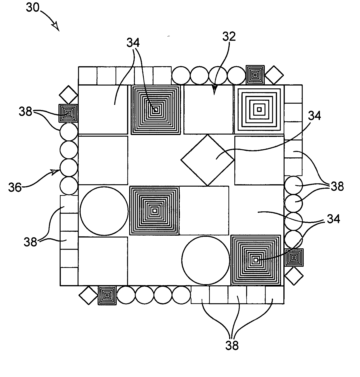
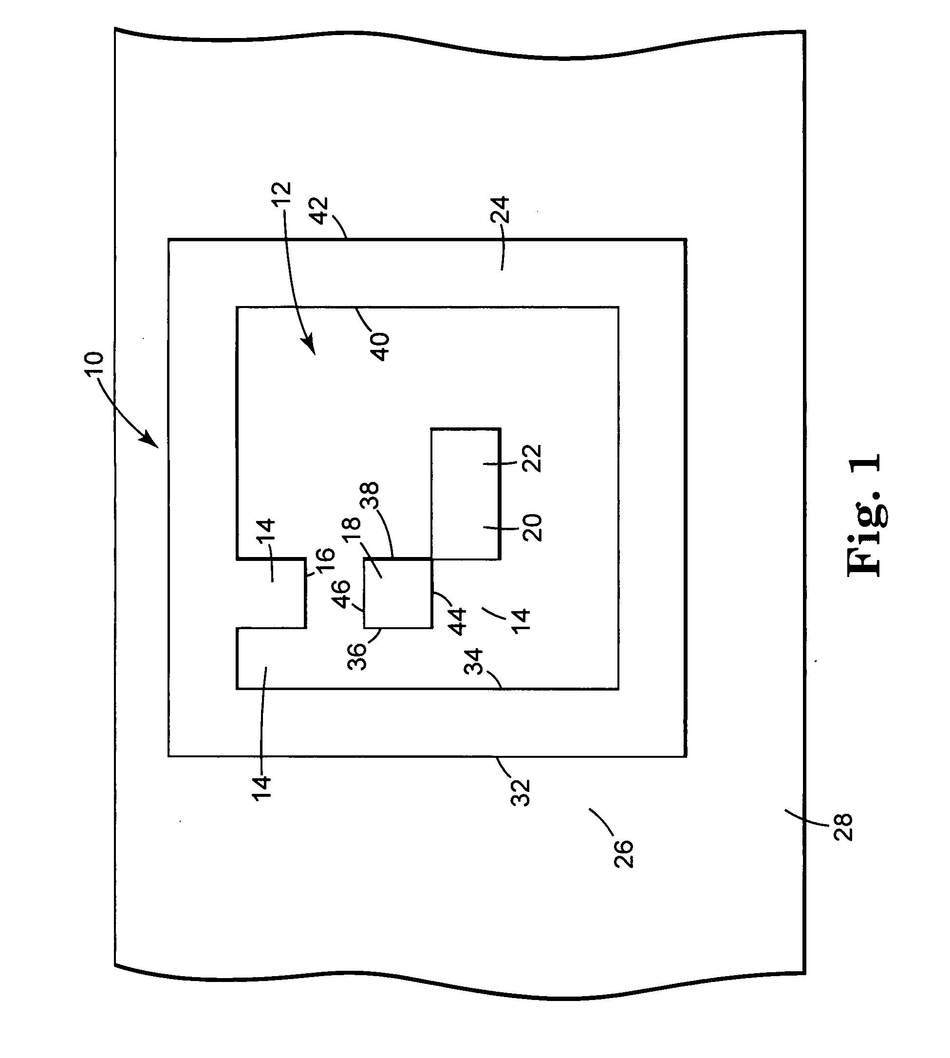
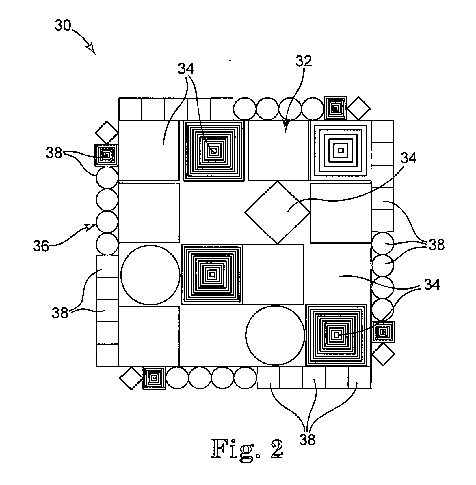
[0033] Area symbologies are well known, such as are described in U.S. Pat. No. 5,612,524, U.S. Pat. No. 4,972,475, and U.S. Pat. No. 4,924,078, the entire disclosures of which are incorporated herein by reference for all purposes. A typical symbol 10 from such an area symbology is illustrated in FIG. 1. Generally, the symbol 10 includes an internal data field 12 with internal data cells 14 arranged in a matrix, which data field 12 and data cells 14 are preferably rectangular as illustrated, although any other shapes are contemplated. As shown, the internal data field 12 has certain data cells 14 that are “on” and certain data cells 14 that are “off.” As shown, the “on” cells are black (the cells designated by reference numerals 16, 18, 20, and 22) while the “off” cells are white (the remaining cells of the internal data field 12). Such on and off designations are used in decoding a symbol such as the symbol 10. It is understood that any binary designation may be used for differentia...


PUM


Abstract

Multi-dimensional symbology codes that use plural characteristic features encoded in a data cell and related methods. Such methods include methods of encoding, methods of creating and methods of reading multi-dimensional symbology codes that use such plural characteristic features. The features, for example, include colors, grey scale levels, cell shape, patterns within a cell or any grouping discernable by an area array camera or similar device.

Description

CROSS-REFERENCE TO RELATED APPLICATION [0001] The present application claims priority to U.S. Provisional Application No. 60 / 813,769, filed Jun. 14, 2006, the contents of which are incorporated herein by reference in its entirety for all purposes.TECHNICAL FIELD [0002] The present invention relates to methods for encoding and decoding information. In particular, the present invention relates to multi-dimensional matrix coding technology. BACKGROUND [0003] Modern bar code work began in 1948. On Oct. 20, 1949, Woodland and Silver filed a patent application entitled “Classifying Apparatus and Method.” The inventors described their invention as relating “to the art of article classification . . . through the medium of identifying patterns.” Woodland and Silver bar code was a bull's eye symbol, a symbol made up of a series of concentric circles. Woodland and Silver also described a straight-line pattern quite similar to present day one-dimensional bar codes. The symbology was made up of ...

Claims


Application Information

Patent Timeline
Patent Type & Authority Applications(United States)
IPC IPC(8): G06K7/01
CPCG06K19/06037G06K2019/06225G06K19/06046G06K7/10
Inventor LOOK, THOMAS F.
Owner VERITEC INCORPORATED
Why Eureka
Try Eureka