

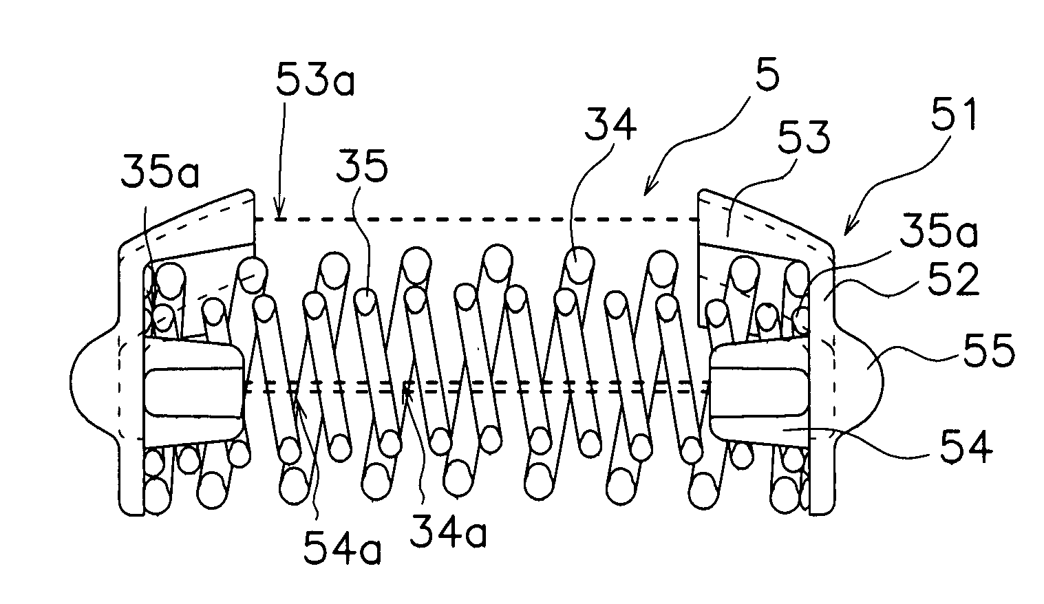
Spring seat and spring assembly
a spring assembly and seat technology, applied in the direction of wound springs, machine supports, other domestic objects, etc., can solve the problems of deterioration in sound vibration performance of damper mechanism, affecting the performance and the position of small coil springs within the large coil springs may not be stabilized, so as to achieve the effect of easy support of small coil springs
- Summary
- Abstract
- Description
- Claims
- Application Information
AI Technical Summary
Benefits of technology
Problems solved by technology
Method used
Image

Examples
Embodiment Construction
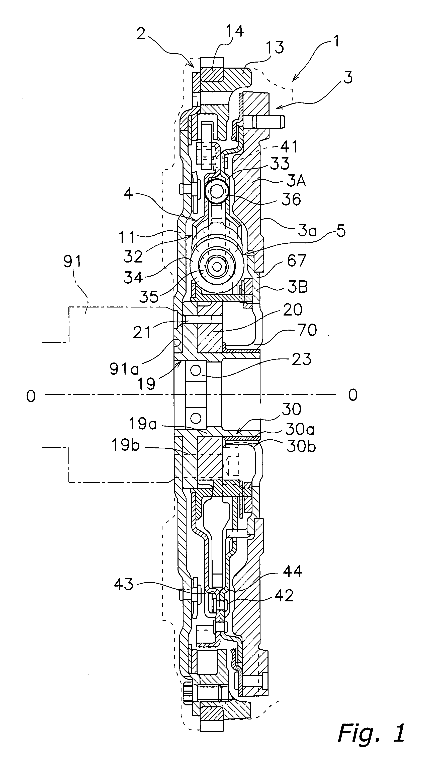
[0033]Selected embodiments of the present invention will now be explained with reference to the drawings. It will be apparent to those skilled in the art from this disclosure that the following descriptions of the embodiments of the present invention are provided for illustration only and not for the purpose of limiting the invention as defined by the appended claims and their equivalents. Embodiments of a spring assembly 5 being adapted in the present invention will be explained hereinafter with reference to the attached drawings.
Overall Configuration of a Dual Mass Flywheel
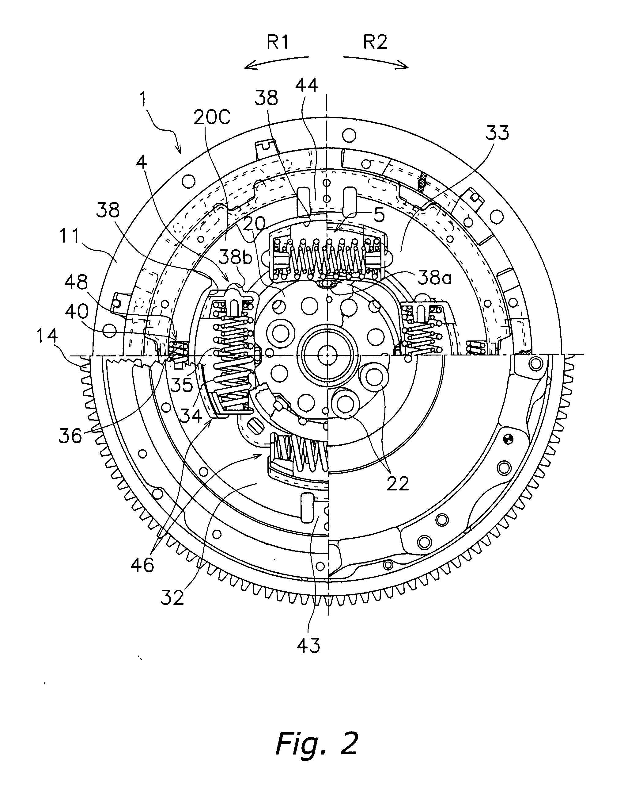
[0034]A dual mass flywheel 1 includes a spring assembly 5, which has been adapted to an embodiment of the present invention shown in FIG. 1. The dual mass flywheel 1 serves as a damper for transmitting torque from a crankshaft 91 that is provided at an engine side to an input shaft (not shown), which is provided at a transmission side through a clutch (clutch disc assembly and clutch cover assembly). The dual ma...
PUM
 Abstract
Description
Claims
Application Information