Check patentability & draft patents in minutes with Patsnap Eureka AI!

Ink jet head

a jet head and jet head technology, applied in the field of jet head, can solve the problems of failure of ink ejection upon air intake failure of ink ejection in the pressure chamber, etc., and achieve the effect of good print quality

Inactive Publication Date: 2008-02-14
TOSHIBA TEC KK
View PDF3 Cites 18 Cited by
  • Summary
  • Abstract
  • Description
  • Claims
  • Application Information

AI Technical Summary

Benefits of technology

[0010]An object of the present invention is to provide an ink jet head which can eject an ink droplet while preventing failure of an ink ejection, and print an image having a good print quality.

Problems solved by technology

Therefore the ink jet head poses failure of ink ejection upon the air intake.
Besides, in case that a waste or a foreign matter remains in a process of manufacturing the ink jet head, or ink includes a foreign matter, the nozzle occasionally clogs with the waste or the foreign matter, posing ejection failure.
Furthermore, repetition of applying the ink ejection pulse causes the actuator to generate beat slightly, resulting in lowering viscosity of ink in the pressure chamber.
Since characteristic of the ink ejection is changed by the variation of the viscosity, the ink jet head still poses the other problem that quality of printed characters and images is made inconsistent.
Thus, a complicated management of the elements and a periodic maintenance are required to keep the system work well.
Furthermore, since the plural tubes are needed to fluidly communicate between respective elements in the system, a lot of unavailable ink remains in the tubes as a waste ink.

Method used


Image

  • Ink jet head
  • Ink jet head
  • Ink jet head

Examples


first embodiment

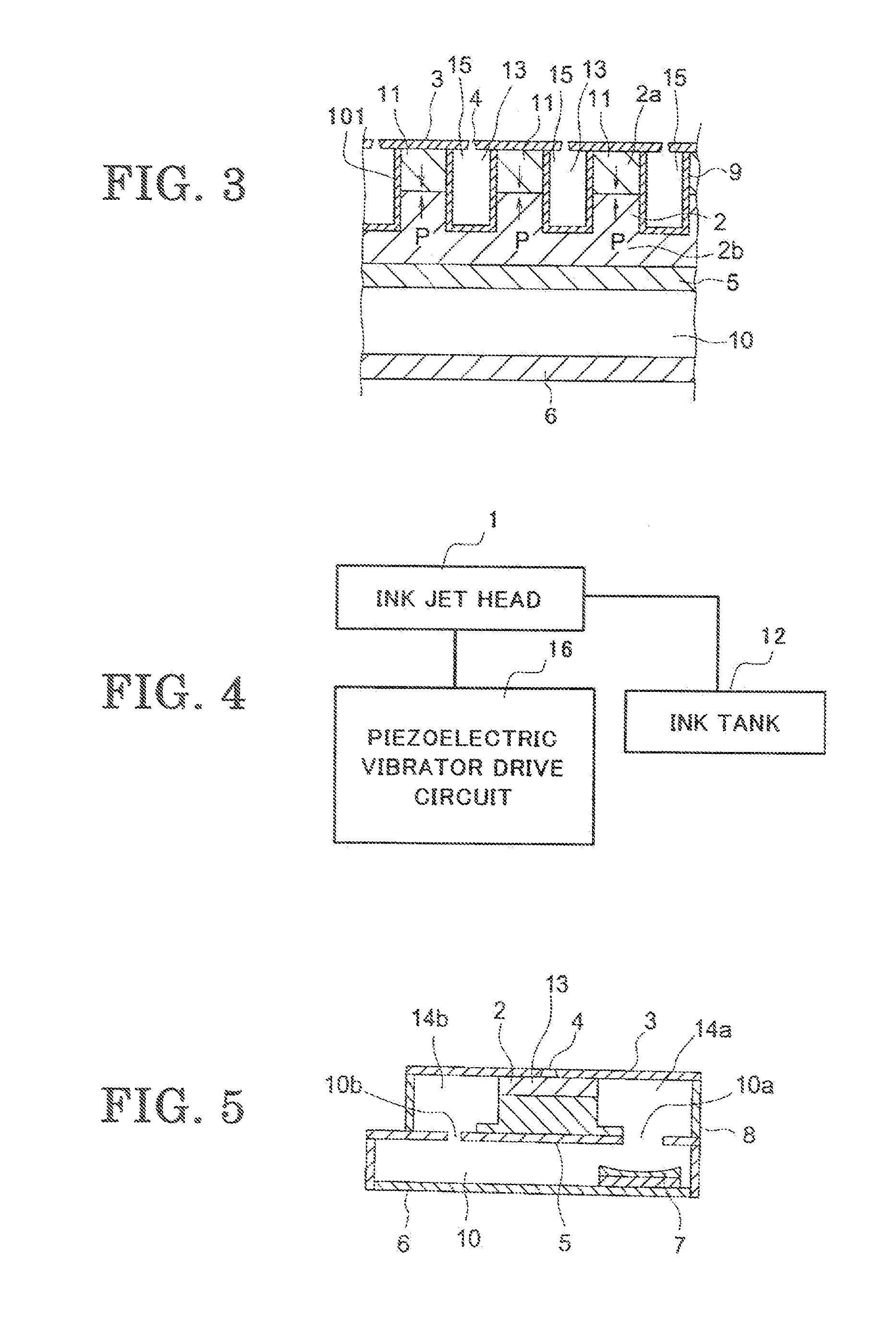
[0065]FIG. 7 shows a cross sectional view of ultrasonic transducer 7 provided in ink channel 10. Ultrasonic transducer 7 is affixed to an inside surface of housing 6 such that it faces to first opening 10a through which ink passes from ink channel 10 to first common ink chamber as indicated by arrow “a.” Housing 6 is made of a lead zirconium titanate. The material of housing 6 including a metal, resin, glass, ceramic, and so on, may be available.

[0066]Ultrasonic transducer 7 includes a piezoelectric vibrator 20 as a source of ultrasound. Piezoelectric vibrator 20 is formed in a flat shape and has an electrode 102 on both surfaces thereof. Piezoelectric vibrator 20 is connected through a lead wire 27 with a piezoelectric vibrator drive circuit 16 provided outside ink jet head 1 to apply a drive signal to electrode 102. Applying the drive signal causes piezoelectric vibrator 20 to radiate an ultrasound from the both surfaces in a direction orthogonal to the surface. Piezoelectric vibr...

second embodiment

[0078]A second embodiment in the present invention will now be described.

[0079]With reference to FIG. 16, ultrasonic transducer 7 comprises a case 24, a laminated material 7a including piezoelectric vibrator 20 and matching member 21, and a ultrasonic absorbent 22 with which a space surrounded by case 24 and laminated material 7a is filled. Ultrasonic transducer7 is affixed on an inside surface of housing 6 to propagate an ultrasound to ink in ink channel.

[0080]Laminated material 7a is formed in a concaved shape such that one surface thereof facing first opening 30 is concaved to converge the ultrasound therefrom in the ink flow direction. The shape of laminated material 7a forms an acoustic lens to converge the ultrasound. Since the ultrasound propagated from laminated material 7a is focused on in the vicinity of first, opening 10a, ink in channel 10 can be effectively conveyed toward first opening 10a with less power supplied to ultrasonic transducer 7.

[0081]Incidentally laminated...

third embodiment

[0087]A third embodiment will now be described with reference to FIG. 23. Piezoelectric vibrator 20 is affixed on an outside surface of housing 6 at a position that an ultrasound propagated from piezoelectric vibrator 20 is directed to first opening 10a. A concave surface 27 is formed on an inside surface of housing 6 at the position. In other words, piezoelectric vibrator 20 and a part of housing 6 are integrated into ultrasonic transducer 7. A concave acoustic lens is formed of both the outside surface provided with piezoelectric vibrator 20 and the inside surface opposite the outside surface to converge the ultrasound in the vicinity of first opening 10a. It is preferred to select a material of housing 6 having a specific acoustic impedance less than that of piezoelectric vibrator 20 and larger than that of the ink, since housing 6 further serves as a matching member.

[0088]Incidentally, although housing 6 in which an inside surface includes a concave surface is exemplified, other...


PUM


Abstract

Disclosed is an ink jet head which can eject an ink droplet while preventing failure of ink ejection, resulting in printing an image having good print quality. The ink jet head comprises a plurality of pressure chambers, a nozzle fluidly communicating with respective pressure chamber, first common ink chamber provided on one edge of the pressure chamber, second common ink chamber provided on the other edge of the pressure chamber, and an ink channel fluidly communicating the first common ink chamber with the second. An ultrasonic transducer arranged in a part of the ink channel causes the ink in ink channel to circulate through a passage way formed of the ink channel, the first and second common, ink chambers and pressure chamber.

Description

BACKGROUND OF THE INVENTION[0001](1) Field of the Invention[0002]The present invention relates, in general, to an ink jet head, and in particular, to an ink jet head including an ink circulating passage way therein.[0003](2) Description of the Related Art[0004]In recent years, printers on which an ink jet head is mounted to eject an ink droplet to record an image on a medium are widely popularized in various fields including an industry, a home appliance, and so on. Since the ink jet head readily realizes images in grey scale and in color and has its low running cost the prospect for the future thereof is remarkable.[0005]In the field of an ink jet printer, a Drop-On-Demand (D-O-D) ink jet head is currently a major one.[0006]Japanese Laid-open patent application (KOKAI) PH11-207972 discloses a D-O-D ink jet head comprising a pressure chamber connected to a nozzle in a fluid communication to eject an ink droplet from the nozzle. The pressure chamber is formed of a nozzle plate having...

Claims


Application Information

Patent Timeline
IPC IPC(8): B41J2/045
CPCB41J2202/12B41J2/14209
Inventor TANUMA, CHIAKI
Owner TOSHIBA TEC KK
Features
  • R&D
  • Intellectual Property
  • Life Sciences
  • Materials
  • Tech Scout
  • Unparalleled Data Quality
  • Higher Quality Content
  • 60% Fewer Hallucinations
Learn More