Polarizer and liquid crystal display employing same

a technology of liquid crystal display and polarizer, which is applied in the direction of optics, instruments, optical elements, etc., can solve the problems of approximately 50% of the light beams emitted by the backlight module being lost before reaching the liquid crystal layer, and the liquid crystal used in lcds is not self-luminescen

Inactive Publication Date: 2008-02-14
HON HAI PRECISION IND CO LTD
View PDF8 Cites 7 Cited by
  • Summary
  • Abstract
  • Description
  • Claims
  • Application Information

AI Technical Summary

Problems solved by technology

However, liquid crystals used in LCDs are not self-luminescent.
Thus, approximately 50% of the light beams emitted by the backlight module are lost before reaching the liquid crystal layer.

Method used


Image

  • Polarizer and liquid crystal display employing same
  • Polarizer and liquid crystal display employing same
  • Polarizer and liquid crystal display employing same

Examples


first embodiment

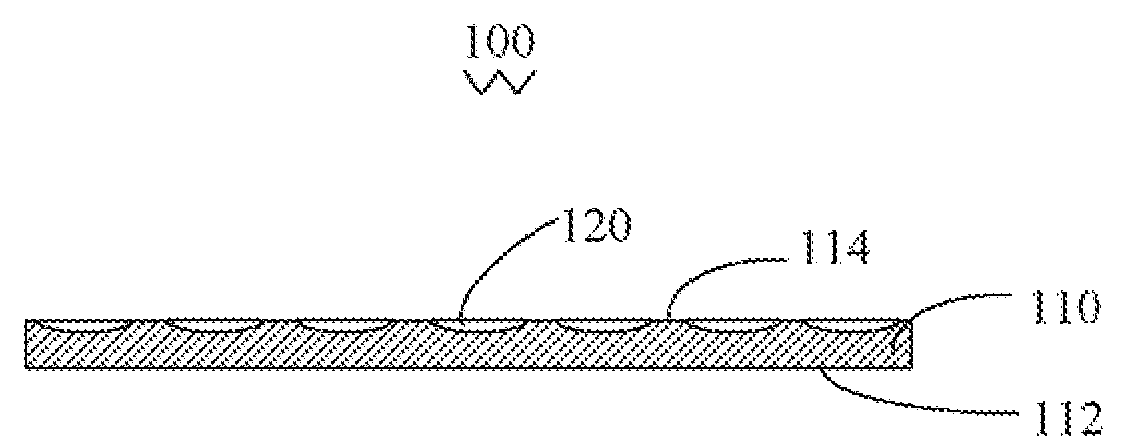
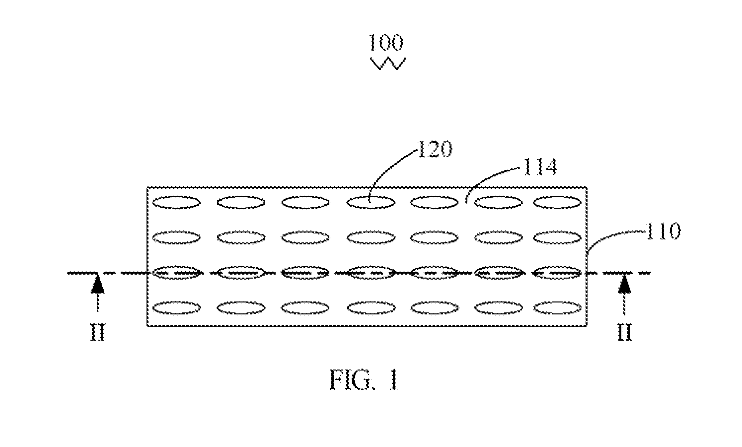
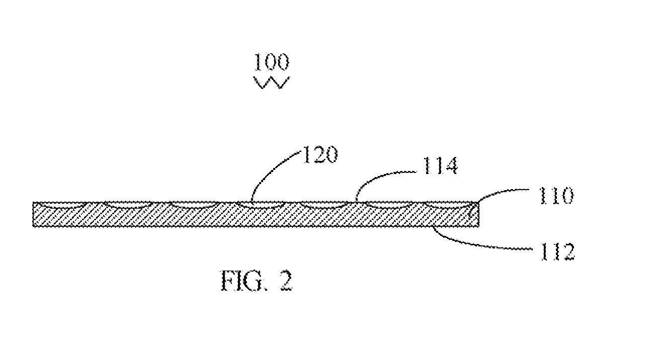
[0018]Referring to FIGS. 1 and 2, a polarizer 100 is shown. The polarizer 100 includes an optical anisotropic transparent substrate 110. The substrate 110 includes a light incident surface 112 and a light emitting surface 114. The light emitting surface 114 is opposite to the light incident surface 112. The substrate 110 defines a plurality of grooves 120 in the light emitting surface 114. The grooves 120 are oriented in an essentially identical direction.

[0019]The substrate 110 should at least allow visible light (i.e., with a wavelength from 390 to 760 nanometers) to pass therethrough. A thickness of the substrate 110 is in an approximate range from 1 to 10 millimeters (mm), and is more preferably in an approximate range from 2 to 5 mm. In the present embodiment, a material of the substrate 110 is calcite. The calcite allows a light with a wavelength in an approximate range from 350 to 2300 nanometers (nm) to pass therethrough. Alternatively, the material of the substrate 110 may...

second embodiment

[0021]Referring to FIG. 3, a polarizer 200 is shown. The polarizer 200 is similar to the polarizer 100, but further includes an antireflective coating 230 on the light emitting surface 214. The antireflective coating 230 allows a visible light to pass therethrough. The antireflective coating 230 includes a first titanium dioxide coating with a thickness in an approximate range from 10 to 16 nm formed on the light emitting surface 214, a first silicon dioxide coating with an approximate thickness of 26 to 32 nm formed on the first titanium dioxide coating, a second titanium dioxide coating with an approximate thickness of 80 to 120 nm formed on the first silicon dioxide coating, and a second silicon dioxide coating with an approximate thickness of 78 to 86 nm formed on the second titanium dioxide coating. Interference between multiple coatings of the antireflective coating can decrease reflection of incident light.

[0022]The coating step may be a vacuum coating process. The vacuum co...


PUM

PropertyMeasurementUnit
thicknessaaaaaaaaaa
aspect ratioaaaaaaaaaa
depthaaaaaaaaaa

Abstract

A polarizer includes an optical anisotropic transparent substrate. The substrate includes a light incident surface, a light emitting surface and a plurality of substantially elliptical grooves defined in the light emitting surface. The light emitting surface is opposite to the light incident surface. The elliptical grooves are oriented in an essentially identical direction. Each elliptical groove has a major axis and a minor axis. A length of the major axis is essentially equal to or greater than a wavelength of incident light, and a length of the minor axis is less than the wavelength of the incident light.

Description

BACKGROUND OF THE INVENTION[0001]1. Field of the Invention[0002]The present invention generally relates to polarizers and liquid crystal displays (LCDs) using the same.[0003]2. Description of Related Art[0004]Although most portable electronic devices such as laptop and notebook computers, mobile phones and game devices have viewing screens which are unlike the cathode-ray-tube (CRT) monitors of conventional desktop computers, users generally expect the viewing screens to provide performance equal to that of CRT monitors. To meet this demand, computer manufacturers have sought to build flat panel displays (FPDs) offering superior resolution, color and contrast, while at the same time requiring minimal power consumption. LCDs are one type of FPDs which satisfy these expectations. However, liquid crystals used in LCDs are not self-luminescent. Rather, LCDs generally need a surface-emitting device such as a backlight module which can offer sufficient luminance (i.e., brightness) in a wi...

Claims


Application Information

Patent Timeline
Patent Type & Authority Applications(United States)
IPC IPC(8): G02F1/1335
CPCG02F1/133528G02B5/3083
Inventor CHEN, GA-LANE
Owner HON HAI PRECISION IND CO LTD
Why Eureka
Try Eureka