Modular optical light line unit

a module and optical technology, applied in waveguides, instruments, printing, etc., can solve the problems of difficult replacement of light sources, difficult to achieve high uniformity using standard techniques, and patents that do not address the way to join two or more units to produce a very long linear beam

Inactive Publication Date: 2008-02-14
ILLUMINATION TECH
View PDF2 Cites 32 Cited by
  • Summary
  • Abstract
  • Description
  • Claims
  • Application Information

AI Technical Summary

Benefits of technology

[0007]It is an object of the present invention to provide a lightline arrangement that creates a continu

Problems solved by technology

However, that patent does not address how to join two or more units to produce a very long linear beam.
Such high uniformity has been difficult to achieve using standard techniques, such as apertured fluorescent lamps.
In addition, inspection of heat-sensitive materials requires remoting the light source from the product, and this has been impossible where conventional linear light sources need to be in proximity to the

Method used


Image

  • Modular optical light line unit
  • Modular optical light line unit
  • Modular optical light line unit

Examples


Embodiment Construction

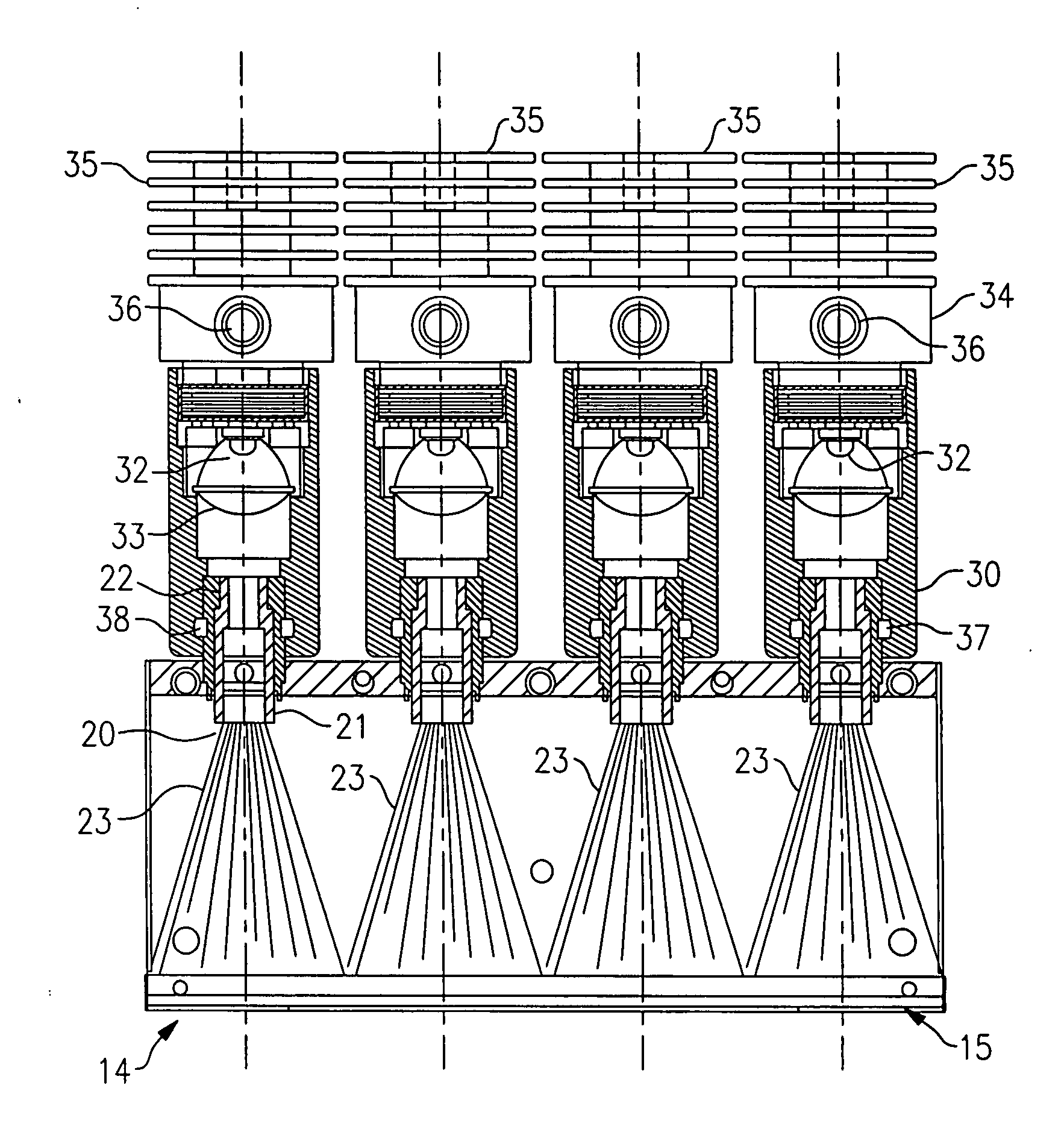
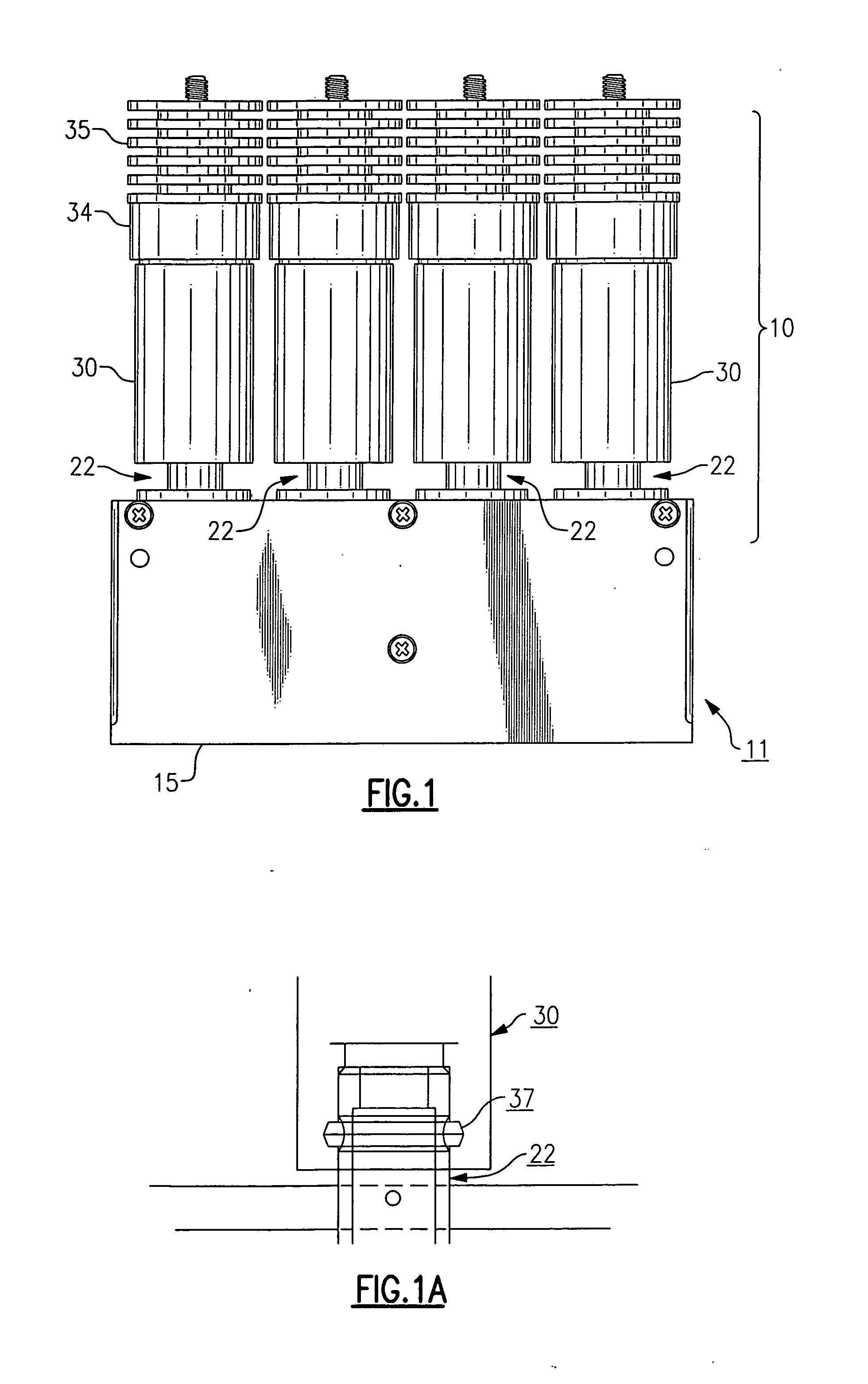
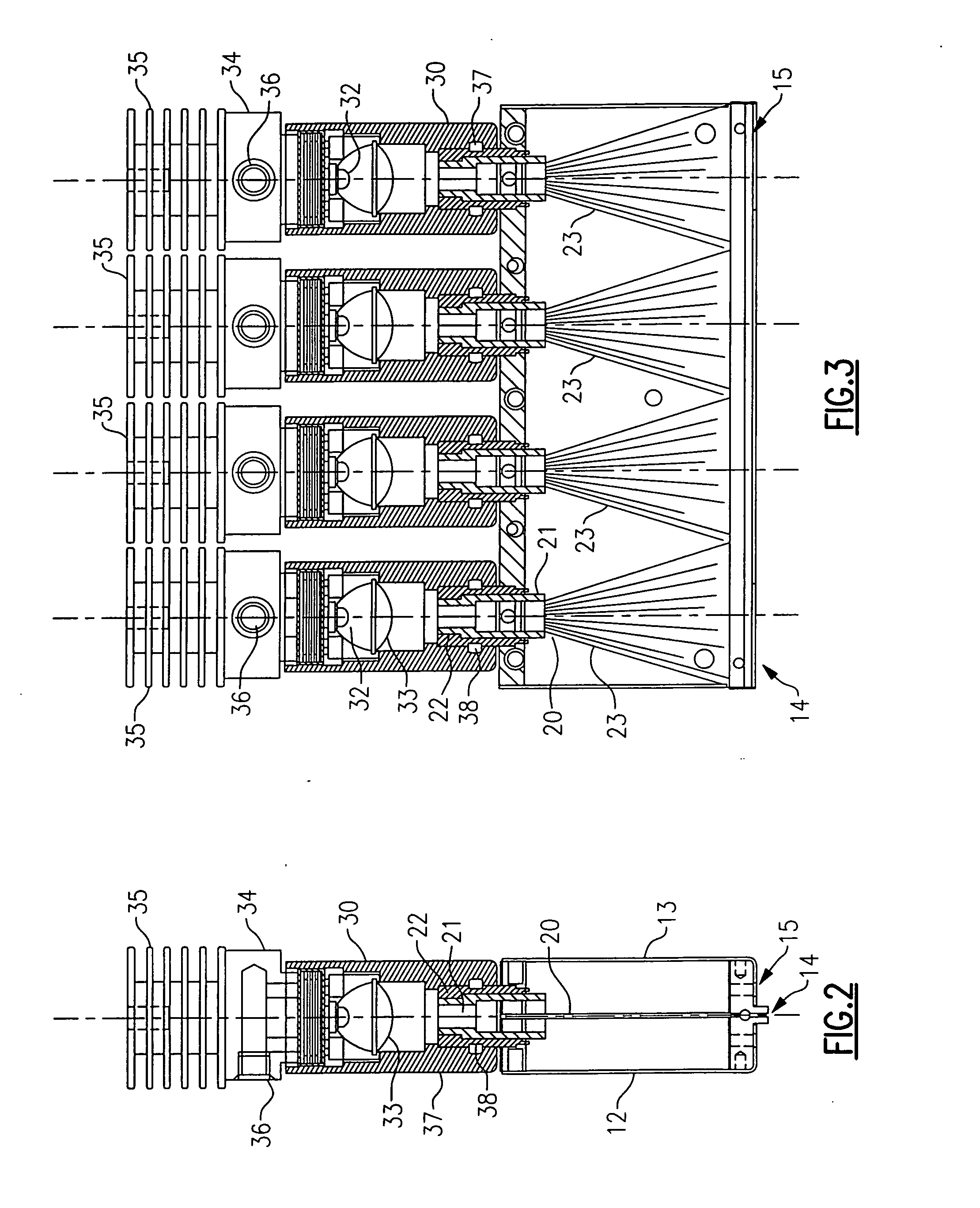
[0023]With reference to FIGS. 1 to 3 of the Drawing, a modular light line unit 10 has a housing or casing 11 formed of a first housing half 12 and a second housing half 13. These halves 12, 13, better viewed in FIG. 2, are preferably made of a cast anodized aluminum, although many other suitable materials exist. The halves fit together at a join line 14. At a lower or distal side of the housing 11 forms an elongated flat distal face 15, where the join line 14 defines a light line, and from the latter emanates the light line or linear beam of illumination.

[0024]As shown in FIGS. 2 and 3, there is at least one fiber optic bundle 20 contained in the housing 11, and in this embodiment there are four bundles 20. Each fiber optic bundle 20 has a proximal or upper end 21, which is bound and housed within a ferrule 22. In this embodiment there are four ferrules 22, and each projects out the upper or proximal side of the housing or casing 11. Within the housing 11, a distal portion 23 of eac...


PUM


Abstract

A modular fiber optic light line unit has a housing in which distal portions of one or more fiber optic bundles fan out such that termini of the fibers are arrayed in a continuous fiber row. The proximal ends of the bundles are held in respective sleeves, and light source modules are removably attached over the sleeves to generate light that is incident on the proximal end of the bundle. The light source modules are removably installed by pushing on, without requiring tools. The light source modules have a canister housing containing a solid-state light source, e.g., five watts. Heat management is achieved using fins on the modular housing. Different color wavelength light sources can be employed, and the fibers from the various bundles can be interleaved.

Description

BACKGROUND OF THE INVENTION[0001]This invention relates to apparatus for illuminating an object and for providing a uniform, thin line of light onto an object for line scan applications. The invention relates to light line units of modular design that can used individually or can be butted end to end to provide very long, seamless linear beams of light. The invention is more particularly directed to an optical fiber based unit which includes an internal light source and where the fibers convert the illumination from that source into a thin, long line of light.[0002]Modular light line units of this general type are discussed in U.S. Pat. No. 5,550,946. In the modular units of that design, there is a bundle of optical fibers that fan out into a single row of fibers, in a manner that allows the units to be placed end to end to create a long line of light. The housings for these light line units are in the form of top and bottom jaws, and these jaws may be formed with triangular teeth t...

Claims


Application Information

Patent Timeline
IPC IPC(8): G02B6/40G02B6/43F21V29/00
CPCG02B6/0008G02B6/4298G02B6/4292G02B6/4249Y10S385/901
Inventor MUEHLEMANN, MICHAEL MARKTHOMAS, DARRYL ALEXANDERCATTERFELD, ROBERT JOHN
Owner ILLUMINATION TECH
Why Eureka
Try Eureka