Electronic stethoscope

a technology of stethoscope and stethoscope body, which is applied in the field of stethoscope, can solve the problems of not being widely used by medical personnel, consuming too much power, weighing too much, etc., and achieves the effect of improving performance characteristics

Inactive Publication Date: 2008-02-14
GRASFIELD JAMES A +4
View PDF0 Cites 19 Cited by
  • Summary
  • Abstract
  • Description
  • Claims
  • Application Information

AI Technical Summary

Benefits of technology

[0010] The present invention overcomes the disadvantages of the prior art by providing an electronic stethoscope that closely resembles a typical acoustic stethoscope. The present invention feels and operates, to a user, like an acoustic stethoscope, but with enhanced performance characteristics.
[0014] The electronic stethoscope may also have a “murmur enhancement” operational mode in which the electronic signals from the bandpass filter are processed by an automatic gain control circuit and then transmitted to the low pass filter. The murmur enhancement mode allows the stethoscope to disproportionately amplify, relative to heart sounds generated by normal cardiac activity (i.e., for example, so called “dominant” or “first” and “second” heart sounds), heart sounds generated by abnormal cardiac activity (i.e., for example, murmur sounds) while at the same time not amplifying the volume of the normal cardiac activity. This allows the user to more clearly determine the relationship between the abnormal heart sound and the normal heart sound. This has the effect of amplifying the low level murmur activity without significantly amplifying the normal cardiac activity. This mode of operation also allows a user to hear heart murmurs more clearly. This mode of operation also allows a user to hear heart sounds that may be inaudible or difficult to hear using a typical acoustic stethoscope. In one embodiment, the automatic gain control circuit has a response time constant in the range of 5 to 100 ms.
[0016] In other embodiments, the electronic stethoscope includes a transceiver, coupled between the bandpass filter and the processing system for transmitting electronic signals from the bandpass filter to a remote device and / or receiving electronic signals from a remote device to be processed by the processing system. In this way, the electronic stethoscope can transmit the entire spectrum of electronic signals being detected to another stethoscope or multiple stethoscopes so that more than one user can participate in the diagnostic process. In the same manner the electronic stethoscope can receive electronic signals so that a user can hear these received signals and individually, independently, and simultaneously process the received signals. This allows, among other things, real-time transmission and reception of the electronic signals, so that several users can participate in the diagnostic process simultaneously.
[0017] Another feature of the electronic stethoscope of the invention is a switch for controlling power including a first pole of the switch attached to a first binaural in the pair of binaurals of the stethoscope and a second pole of the switch attached to a second binaural in the pair of binaurals. A spring is mechanically coupled to each binaural and, in a rest position, urges the first and second binaurals together. When the closing force of the spring is overcome and the binaurals are separated by a predetermined distance, the first pole and the second pole make electrical contact to supply electrical power to the signal processing circuitry. Upon release of the binaurals, the spring urges the binaurals together and the first pole and second pole are separated to remove electrical power from the signal processing circuitry. This provides a convenient and familiar way of operating the electronic stethoscope that does not require any new activity or steps compared to an acoustic stethoscope that does not have to be turned on or off.

Problems solved by technology

Despite the availability of electronic stethoscopes, they do not appear to be widely used by medical personnel, such as doctors, nurses, and emergency medical technicians.
Although the reasons for this lack of acceptance are not completely clear, one problem with some presently available electronic stethoscopes may be that they do not reproduce acoustic signals resulting from the operation of various body organs in a manner that is familiar to a trained user.
Other problems with some presently available electronic stethoscopes are that they consume too much power, weigh too much, are too large, or require a user to change the manner in which the stethoscope is used as compared to a conventional acoustic stethoscope.
Some conventional electronic stethoscopes do not reproduce heart and lung sounds with the same spectral characteristics as acoustic stethoscopes.

Method used


Image

  • Electronic stethoscope
  • Electronic stethoscope
  • Electronic stethoscope

Examples


Embodiment Construction

[0038] For purposes of illustration only, and not to limit generality, the present invention will now be explained with reference to an electronic stethoscope for use in heart and lung diagnosis in humans. Specific ranges of operation and frequencies will be discussed in this context. One skilled in the art will appreciate, however, that the present invention is not so limited and that by changing the operational frequencies and other stethoscope parameters, the present invention may be used to diagnose other types of human biological activity as well as biological activity in infants, children, animals, and so on.

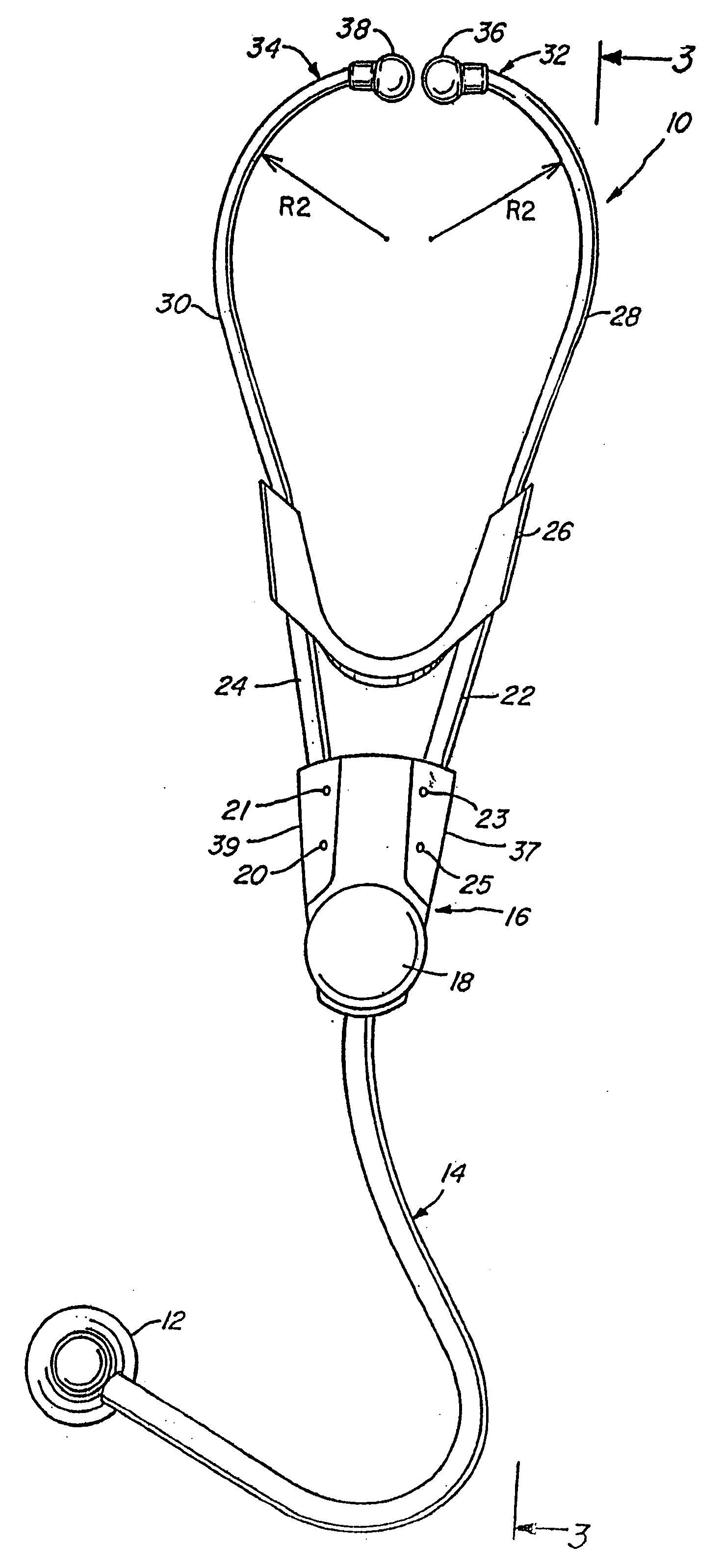
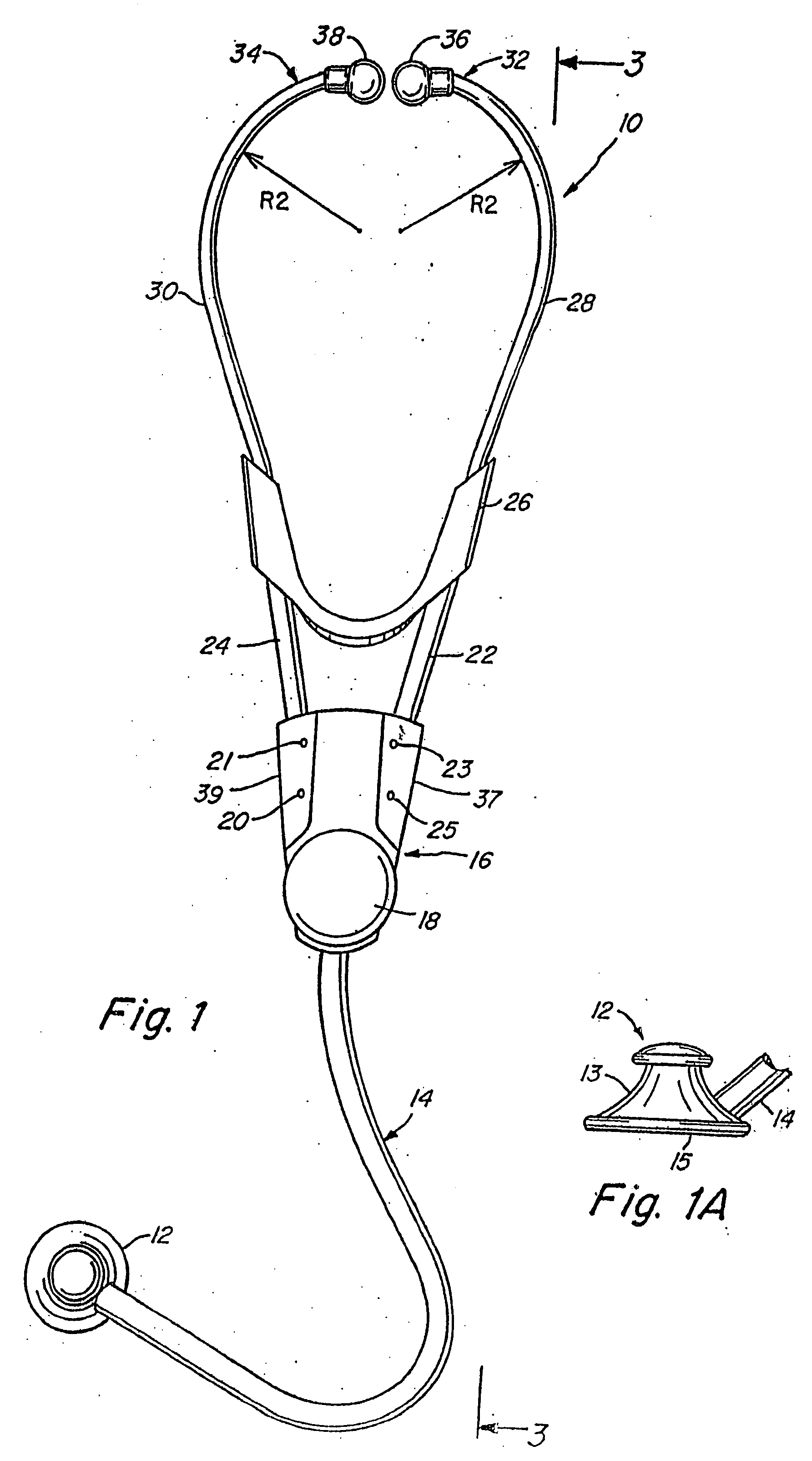
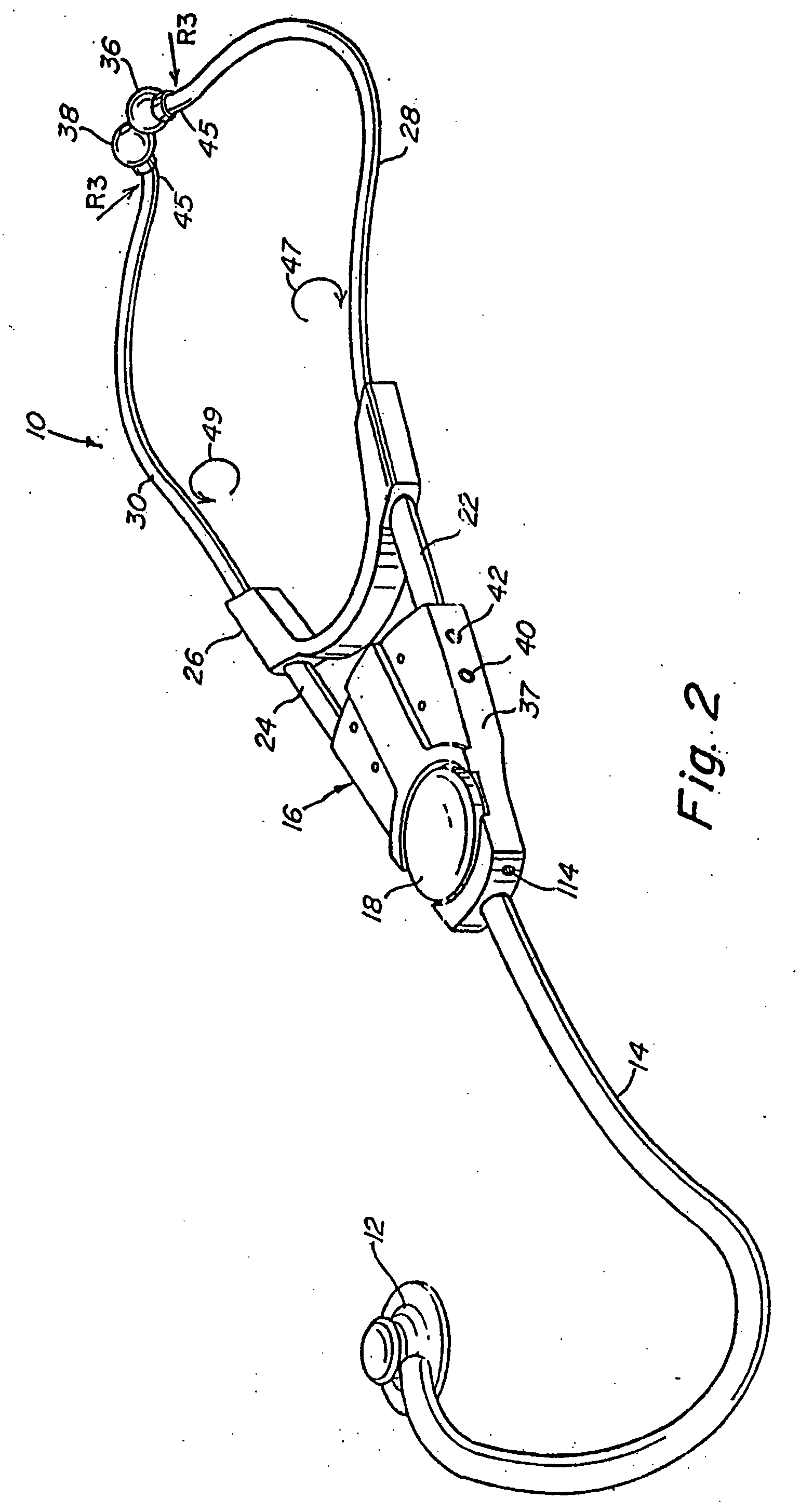
[0039] Reference is now made to FIGS. 1, 2, and 3 which Figures illustrate the overall configuration of the electronic stethoscope of the invention. The electronic stethoscope 10 includes a chestpiece 12 that is used to detect and convert biological activity of particular organs into acoustic pressure waves (i.e., acoustic signals). The acoustic signals are transmitted th...


PUM


Abstract

An electronic stethoscope having several modes of operation to process acoustic signals to provide filtered signals useful for diagnosis. In one mode of operation the stethoscope substantially provides only acoustic signals generated by biological activity of the heart. In another mode of operation, the acoustic stethoscope substantially provides only acoustic signals generated by biological activity of the lungs. In another mode of operation, the electronic stethoscope disproportionately amplifies abnormal heart sounds and normal heart sounds to enhance diagnosis of heart abnormalities. The electronic stethoscope is operated in a manner similar to a conventional acoustic stethoscope and has similar spectral characteristics, thus allowing a user with acoustic stethoscope experience to easily use the electronic stethoscope.

Description

CROSS REFERENCE TO RELATED APPLICATIONS [0001] This application is a continuation of application Ser. No. 11 / 483,152, filed Jul. 7, 2006, which in turn is a continuation of application Ser. No. 11 / 269,128, filed Nov. 8, 2005, which in turn is a continuation of application Ser. No. 11 / 077,540, filed Mar. 9, 2005, which in turn is a continuation of application Ser. No. 10 / 872,143, filed Jun. 18, 2004, which in turn is a continuation of application Ser. No. 10 / 646,521, filed Aug. 22, 2003, which in turn is a continuation of application Ser. No. 10 / 313,967, filed Dec. 6, 2002, which in turn is a continuation of application Ser. No. 10 / 128,149, filed Apr. 23, 2002, which in turn is a continuation of application Ser. No. 09 / 258,263, filed Feb. 25, 1999, which in turn is a continuation of application Ser. No. 09 / 127,992, filed Aug. 3, 1998, which in turn is a continuation of application Ser. No. 08 / 685,451, filed Jul. 19, 1996, which in turn is a continuation-in-part of application Ser. No...

Claims


Application Information

Patent Timeline
Patent Type & Authority Applications(United States)
IPC IPC(8): A61B7/04A61B7/00
CPCA61B7/04A61B7/003
Inventor GRASFIELD, JAMES A.WINSTON, DAVID E.PURBRICK, JOHN A.STARK, PETER R. H.STEINHUBEL, DANIELA
Owner GRASFIELD JAMES A
Why Eureka
Try Eureka