Dynamic Bearing Device

a bearing device and dynamic technology, applied in the direction of sliding contact bearings, generators/motors, instruments, etc., can solve the problems of sliding face wear caused by repeated start and stop of the operation, bearing performance may be degraded, wear is more likely to be accelerated, etc., to prevent the dynamic pressure effect from getting worse, high rotational accuracy, and high durability

Active Publication Date: 2008-02-14
NTN CORP
View PDF10 Cites 7 Cited by
  • Summary
  • Abstract
  • Description
  • Claims
  • Application Information

AI Technical Summary

Benefits of technology

[0013]In the above-described structure, it is desirable to set a ratio: h / r ≦0.01 where a length of the inclined plane in a radial direction is r and a height of the inclined plane is h so as to prevent the dynamic pressure effect from getting worse or the like.
[0014]A motor including: the above-described dynamic bearing device; a rotor magnet attached to the rotational-side member; and a stator coil attached to the fixed-side member has high durability as well as high rotational accuracy. Therefore, the motor is suitable as a motor for information equipment.
[0015]As is apparent from the above description, since wear of the thrust bearing portion can be prevented according to the present invention, the durability of the dynamic bearing device can be improved.

Problems solved by technology

Therefore, in the dynamic bearing device used for information equipment in which the operation of a motor is frequently started and stopped, for example, consumer equipment including an HDD-DVD recorder and a storage device for a cell-phone, the wear of a sliding face caused by repeated start and stop of the operation emerges as a problem under some conditions for use and the like.
In particular, in the case where the flange is made of a resin, wear is more likely to be accelerated as compared with the case where metals slide with each other.
Accordingly, there is a possibility that bearing performance may be degraded within a short period of time due to the effect of abrasion powder.

Method used


Image

  • Dynamic Bearing Device
  • Dynamic Bearing Device
  • Dynamic Bearing Device

Examples


Embodiment Construction

[0025]Hereinafter, embodiments of the present invention will be described.

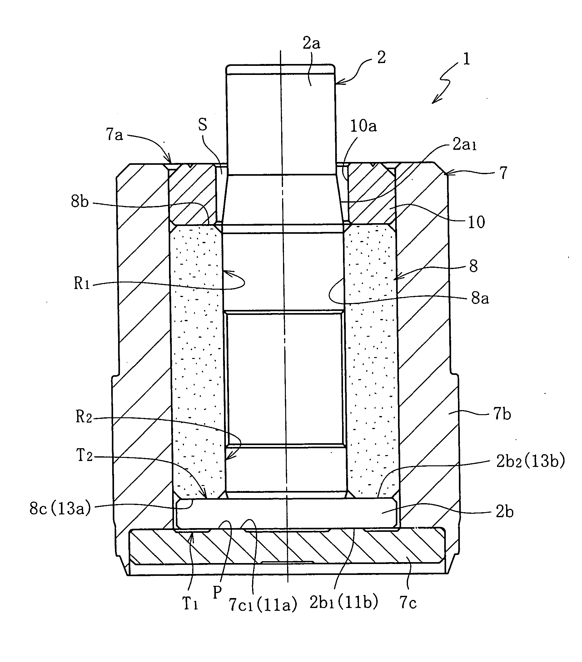
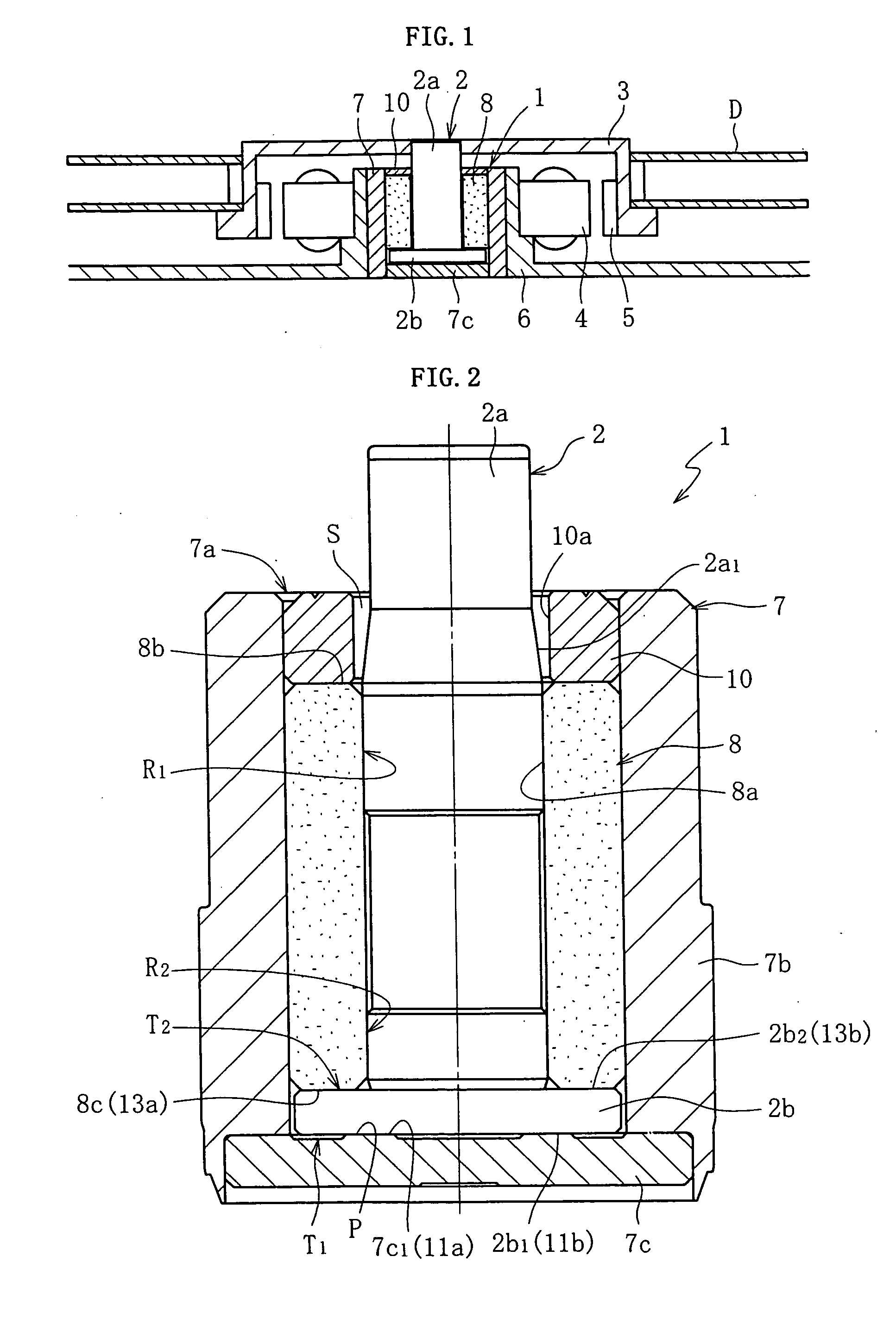
[0026]FIG. 1 shows a spindle motor used for a disk drive device such as an HDD as an example of a spindle motor for information equipment incorporating a dynamic bearing device 1. The motor includes: the dynamic bearing device 1; a rotational member 3 (a disk hub) attached to a shaft member 2 of the dynamic bearing device 1; a stator coil 4 and a rotor magnet 5 provided so as to be opposed to each other, for example, through a radial gap; and a bracket 6. The stator coil 4 is attached to an outer periphery of the bracket 6. The rotor magnet 5 is attached to an inner periphery of the disk hub 3. The disk hub 3 retains one or a plurality of disks D such as a magnetic disk on its outer periphery. A housing 7 of the dynamic bearing device 1 is attached to an inner periphery of the bracket 6. When the stator coil 4 is energized, the rotor magnet 5 is rotated by an excitation force generated between the stator coil ...


PUM

PropertyMeasurementUnit
width Wminaaaaaaaaaa
lengthaaaaaaaaaa
diameteraaaaaaaaaa

Abstract

The present invention has an object of improving wear resistance of a thrust bearing portion. A pressure is generated by a dynamic pressure effect of a lubricating oil in a thrust bearing gap C between a thrust bearing surface 11a including dynamic pressure generating grooves and a smooth thrust receiving surface 11b so as to rotatably support a shaft member 2 in an axial direction. The thrust receiving surface 11b is formed as a flat surface, whereas an inclined plane 17 is provided on the thrust bearing surface 11a so as to provide a reduced portion 15 having a decreasing axial width in a radially outward direction in the thrust bearing gap C.

Description

TECHNICAL FIELD[0001]The present invention relates to a dynamic bearing device. This bearing device is suitable for: a spindle motor for information equipment, for example, a magnetic disk device such as an HDD or an FDD, an optical disk device for a CD-ROM, a DVD-ROM or the like, and a magneto-optical disk device for an MD, an MO or the like; a polygon scanner motor for a laser beam printer (LBP); and a small motor for electric equipment, for example, an axial fan and the like.BACKGROUND ART[0002]The above-mentioned various motors are required to operate not only with high rotational accuracy but also at higher speed, lower cost, and lower noise. One of the components determining the required performance is a bearing for supporting a spindle of the motor. As this type of bearing, a dynamic bearing device having characteristics excellent in the above-mentioned required performance has been considered for use or has been put into practical use in recent years.[0003]As an example of t...

Claims


Application Information

Patent Timeline
Patent Type & Authority Applications(United States)
IPC IPC(8): F16C17/04F16C17/08F16C33/10G11B19/20H02K5/167H02K7/08
CPCF16C17/045F16C17/08F16C33/107F16C2370/12H02K5/1675H02K7/083G11B19/2018F16C17/107F16C17/10F16C32/06H02K7/08
Inventor HAYASHI, TATSUYAKAWASE, TATSUOKUSUNOKI, KIYOTAKAKOMORI, ISAOSHIBAHARA, KATSUO
Owner NTN CORP
Why Eureka
Try Eureka