
Implantable Mri compatible Stimulation Leads And Antennas And Related Systems And Methods

Active Publication Date: 2008-02-14
THE JOHN HOPKINS UNIV SCHOOL OF MEDICINE
View PDF80 Cites 199 Cited by
  • Summary
  • Abstract
  • Description
  • Claims
  • Application Information

AI Technical Summary

Benefits of technology

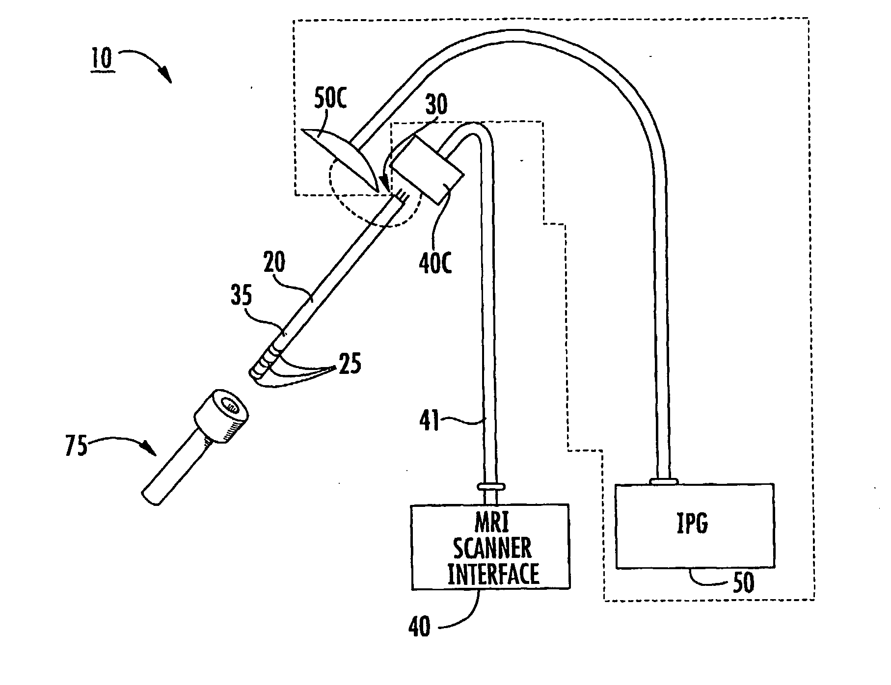
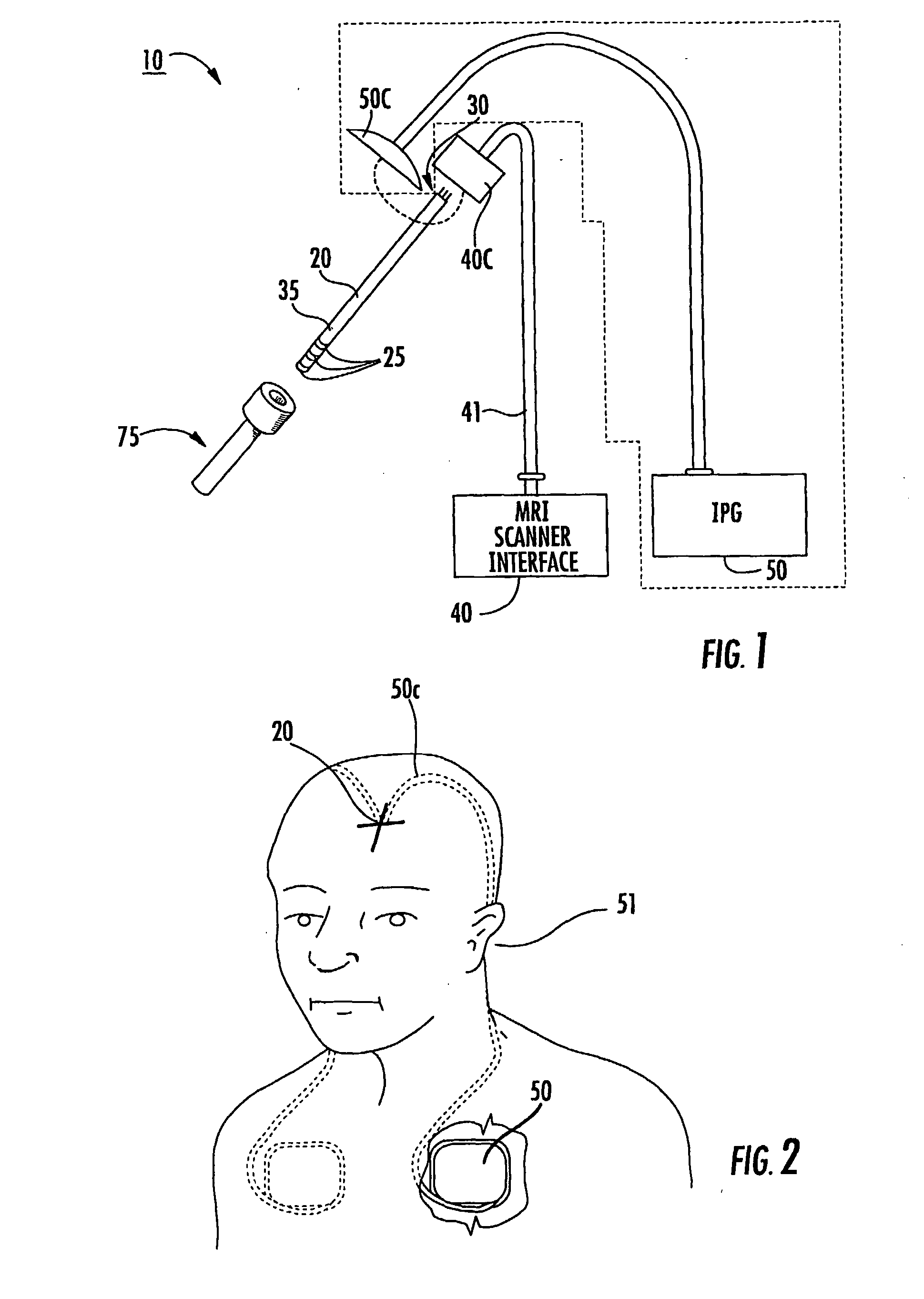
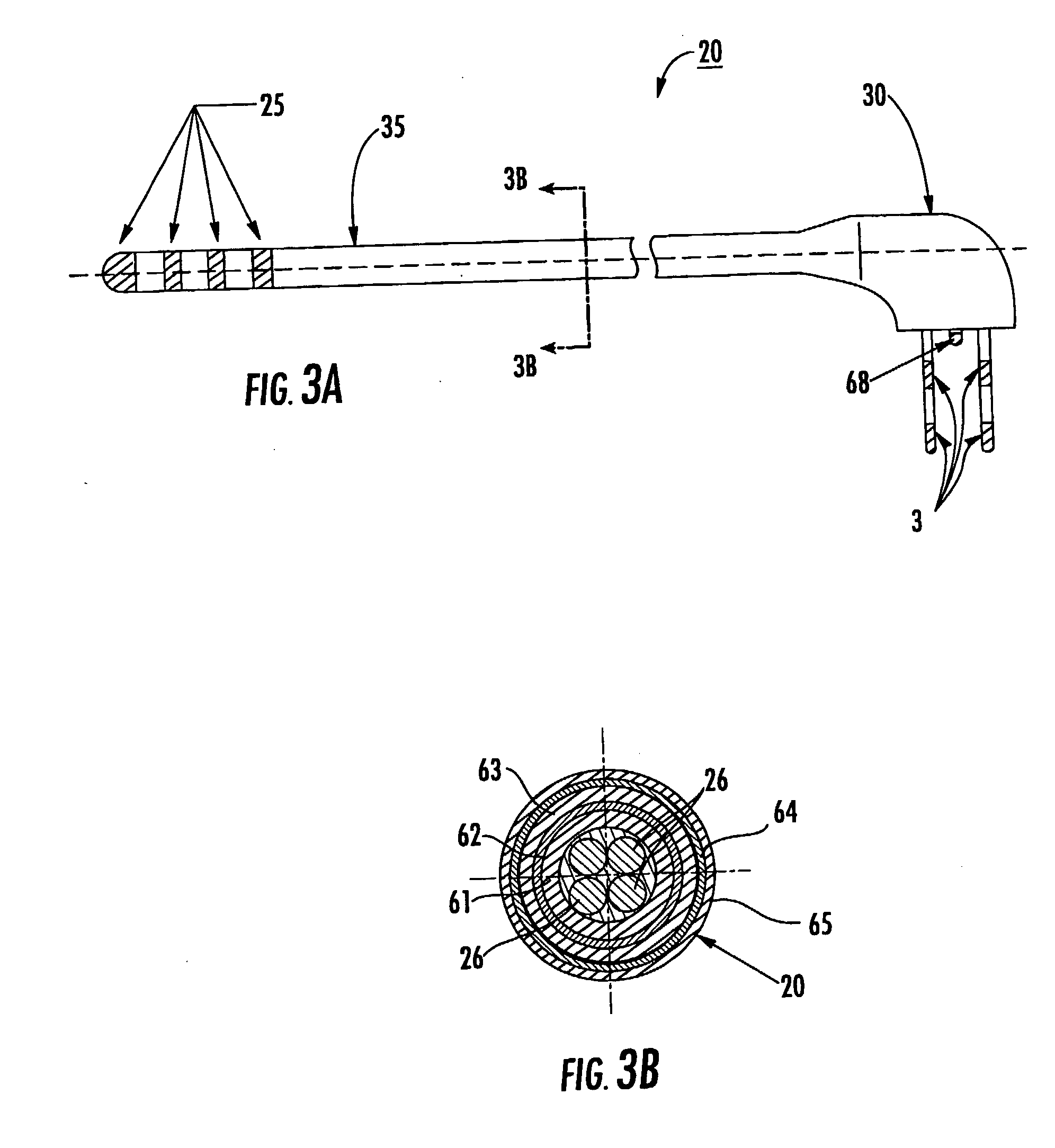
[0012] The device can be a multi-purpose lead system that allows for increased precision placement using an integrated MRI receive antenna and stimulation using electrodes. The lead system can have opposing distal and proximal portions with the proximal portion configured to reside external of the subject during lead placement. In some embodiments, the proximal portion can releaseably attach to either and MRI interface or an implantable pulse generator. The proximal portion can merge into a connector. The distal portion comprises a plurality of stimulating electrodes and an MRI antenna.

Problems solved by technology

However, currently available lead systems may be unsuitable to use in a magnetic resonance imaging (MRI) environment.
For example, the devices may not be MRI compatible, i.e., they may contain ferromagnetic materials, which may distort the MRI images.
Also, currently available lead / probe / cable systems may be susceptible to unwanted induced RF and / or AC current and / or localized heating of the tissue.
Also, the problem of unwanted RF deposition may increase as higher magnetic fields, such as 3 T systems, become more common for MRI imaging (the RF pulses having shorter wavelengths).
However, it has been reported that in about 30% of the patients implanted with these devices, the clinical efficacy of the device / procedure is less than optimum.
This may be attributed to the inaccurate / imprecise placement of the lead / probe / electrode with respect to the cranial or neural tissue.
In certain situations, the lead system may undesirably act as an antenna, picking-up and depositing current in localized tissue where the leads are exposed, thereby potentially increasing the SAR or specific absorption rate (a way of measuring the quantity of radiofrequency (RF) energy that is absorbed by the body).

Method used


Image

  • Implantable Mri compatible Stimulation Leads And Antennas And Related Systems And Methods
  • Implantable Mri compatible Stimulation Leads And Antennas And Related Systems And Methods
  • Implantable Mri compatible Stimulation Leads And Antennas And Related Systems And Methods

Examples


Embodiment Construction

[0010] Some embodiments of the present invention provide therapeutic lead systems. The lead systems may include RF chokes and / or induced current resistant leads. The lead systems may be implantable, MRI compatible multi-purpose lead systems configured to provide an internal MRI receive antenna and at least one stimulating electrode.

[0011] The lead can be a relatively long implantable lead having a length in the body of greater than 10 cm. The at least one electrode can be a plurality of electrodes with at least one being a recording and / or a recording and stimulating and / or ablating electrode.

[0012] The device can be a multi-purpose lead system that allows for increased precision placement using an integrated MRI receive antenna and stimulation using electrodes. The lead system can have opposing distal and proximal portions with the proximal portion configured to reside external of the subject during lead placement. In some embodiments, the proximal portion can releaseably attach ...


PUM


Abstract

In vivo medical stimulation probes include an elongate lead having at least one stimulation electrode disposed on a distal portion thereof. The probes may include a plurality of axially spaced apart RF chokes disposed on and / or in an axially extending shielding layer of the lead in advance of the at least one electrode to inhibit induced RF current from forming and / or traveling along the shielding layer.

Description

RELATED APPLICATIONS [0001] This application claims the benefit of priority to U.S. Provisional Application Ser. No. 60 / 600,020 filed Aug. 9, 2004 and 60 / 608,195, filed Sep. 9, 2004, the contents of which are hereby incorporated by reference as if recited in full herein.GOVERNMENT FUNDING [0002] This invention was made, in part, with United States government support under grant number HL57483 from the National Institutes of Health. The United States government has certain rights to this invention.FIELD OF THE INVENTION [0003] The present invention relates to interventional medical leads and may be particularly suitable for MRI compatible implantable Deep Brain Stimulation (“DBS”) and / or implantable sympathetic nerve chain stimulation leads. BACKGROUND OF THE INVENTION [0004] Deep Brain Stimulation (DBS) is becoming an acceptable therapeutic modality in neurosurgical treatment of patients suffering from chronic pain, Parkinson's disease or seizure, and other medical conditions. Other...

Claims


Application Information

Patent Timeline
IPC IPC(8): A61B5/055
CPCA61B5/055A61B19/201A61B19/5225A61B19/5244A61N2001/086A61B2019/5236A61B2019/5454A61N1/0529A61N1/0534A61B2017/00039A61B34/20A61B90/11A61B90/37A61B2090/374A61B2090/3954A61N1/086
Inventor KARMARKAR, PARAG V.
Owner THE JOHN HOPKINS UNIV SCHOOL OF MEDICINE
Learn More