Medical Equipment, Tubular Insertion Device and Tubular Insertion Device Having the Same Medical Equipment

a technology of medical equipment and insertion device, which is applied in the field of medical equipment, tubular insertion device and tubular insertion device, which can solve the problems of patients burdened, the insertion device is subjected to a surplus rotational torque, and it is difficult for the operator to instantaneously perceive the torque more than the predetermined valu

Inactive Publication Date: 2008-02-14
ASAHI INTECC CO LTD
View PDF32 Cites 23 Cited by
  • Summary
  • Abstract
  • Description
  • Claims
  • Application Information

AI Technical Summary

Benefits of technology

[0018]When the cylindrical body is applied more than the predetermined torque, the torque releases the two-side contact which enables the operator to an integral rotation between the main body and the cylindrical body, thereby rendering the tubular body incapable to rotate so as to protect the tubular body against the torsional buckling.
[0019]When the tubular insertion device is in use, it enables the operator to perceive the release of the two-side contact which enables the operator to the integral rotation between the main body and the cylindrical body, so as to instantaneously perceive that the insertion device is applied more than the predetermined torque.

Problems solved by technology

When the insertion device pushes its distal end portion against the occlusion area or vascular wall upon rotating the insertion device around its axis, there is a possibility that the insertion device is subjected to a surplus rotational torque.
This would make patients burdensome who are therapeutically treated with the insert ton device.
This makes it difficult for the operator to instantaneously perceive the torque more than the predetermined value.
Due to the difficulty of instantaneously perceiving the excessive torque, it may be time-consuming to visually confirm the buckling, which resultantly may delay the replacement of the insertion device so as to prolong the therapeutic operation.
It controls the torque transmission needed to drive the rotary section, but has no structure which enables the operator to instantaneously perceive that the insertion device sustains the torque more than the predetermined value during the use of the insertion device.

Method used


Image

  • Medical Equipment, Tubular Insertion Device and Tubular Insertion Device Having the Same Medical Equipment
  • Medical Equipment, Tubular Insertion Device and Tubular Insertion Device Having the Same Medical Equipment
  • Medical Equipment, Tubular Insertion Device and Tubular Insertion Device Having the Same Medical Equipment

Examples


first embodiment

of the Invention

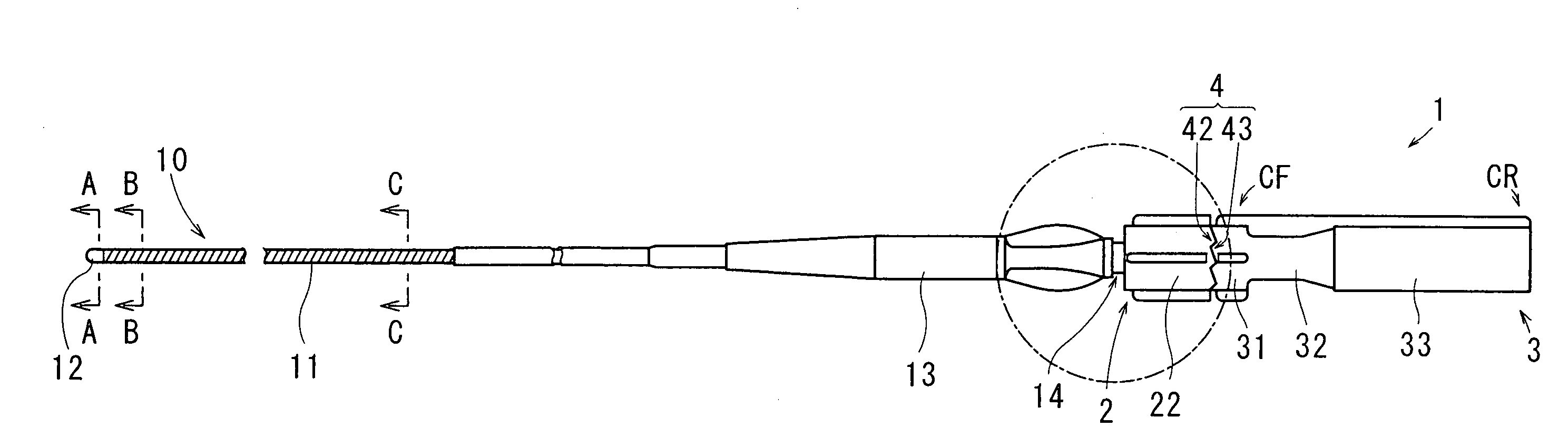
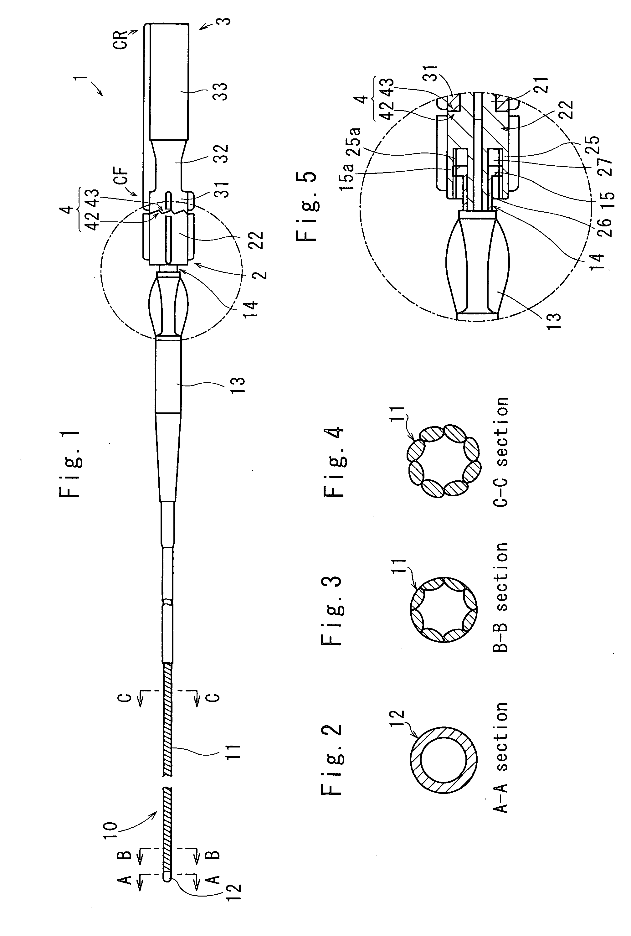
[0061]Referring to FIGS. 1-10 which structurally show a medical equipment 1 according to a first embodiment of the invention, the medical equipment 1 is to be attached to a proximal end portion (right side shown) of an occlusion catheter 10 which serves as a tubular insertion device (tubular lumen insertion device). The occlusion catheter 10 has a shaft portion 11, a part of which forms a helical coil by at least one of winding a metallic wire and stranding metallic wires. The shaft portion 11 has a distal end portion 12 formed by a metallic body at a left end, and having an operative portion 13 at a proximal end of the shaft portion 11 as shown in FIG. 1.

[0062]To be specific, the shaft portion 11 forms a helical coil body. The helical coil body comprises a stranded coil made by closely stranding multiple pieces of a long, thin wire at a constant pitch of approx. Each wire comprising a helical coil body is made of a stainless steel wire. The material for wires is not...

second embodiment

of the Invention

[0129]FIGS. 12-14 show a second embodiment of the invention. In the second embodiment, structures and configuration merely different from those of the first embodiment are described herein. The main body 2 has a body front section (first cylindrical end) BF located at the side where the insertion device is located, and having a body rear section (second cylindrical end) BR located opposite side where the insertion device is located.

[0130]The body front section BF is adapted to come in contact with the cylindrical body front end section CF, and the body rear section BR adapted to come in contact with the cylindrical body rear end section CR. The body front section BF integrally forms the diameter-increased portion 22 on the front end side of the bar portion 21.

[0131]The body rear section BR has a cylindrical interfit elongation 29 provided to the rear end portion of the bar portion 21 discretely from the bar portion 21 and the diameter-increased portion 22. An rear en...

third embodiment

of the Invention

[0169]FIG. 15 show a third embodiment of the invention in which a tubular insertion device 10A is provided. The insertion device 10A has the distal end portion 12 provided at one end of the insertion device 10A, and the shaft portion 11 having the helical coil body at least partly formed by at least one of winding a metallic wire and stranding metallic wires.

[0170]At the other end of the insertion device 10A, the operative portion 13 is rotatably provided to position outside the human body to transmit the rotational movement, of the operative portion 13 to the medical equipment 1.

[0171]The medical equipment 1 has the main body 2, the cylindrical body 3 and the torque regulation mechanism 4. The cylindrical body 3 engages with the main body 2 to integrally rotates in unison with the main body 2. The same manner as described at the second embodiment of the invention, the torque regulation mechanism 4 is provided which releases the integral rotational contact between th...


PUM


Abstract

In a medical equipment (1), tubular insertion device (10A) and tubular insertion device having the medical equipment (1), the medical equipment (1) has a main body (2) regulated to rotate around an axis of the tubular insertion device (10A) and having a cylindrical body (3) provided in contact with the main body (2) to rotate integrally with the main body (2). A torque regulation mechanism (4) is provided to release the integral rotation in unison with the main body (2) so as to block a torque transmission to the tubular insertion device (10A) when a torque applied to the cylindrical body (3) is more than a predetermined value. The block of the transmission renders it incapable to further rotate the tubular insertion device (10A), whereby preventing a torsional buckling from being induced on the insertion device (10A), and enabling the operator to quickly perceive an excessive torque.

Description

[0001]The present application claims priority to Japanese Patent Application No. JP 2006-37162, filed Feb. 14, 2006, the disclosure of which JP incorporated herein by reference in its entirety.FIELD OF THE INVENTION[0002]The invention relates to a medical equipment, tubular insertion device and tubular insertion device having the medical equipment which is attached to the tubular insertion device upon inserting it into a human body.BACKGROUND OF THE INVENTION[0003]Upon therapeutically diagnosing human organs especially such as the blood vessel, the digestive tract, the urethral canal or the like, a tubular insertion device (a.k.a., tubular lumen insertion device) is used which has a flexible and axially elongate body. The operator who inserts the insertion device into the tract of the human body operates the insertion device at the proximal side so as to steer the distal end portion into the tract. The insertion device is represented by a catheter, a guide wire, a balloon catheter o...

Claims


Application Information

Patent Timeline
Patent Type & Authority Applications(United States)
IPC IPC(8): A61B17/00
CPCA61M25/0021A61M25/0136A61M25/0097A61M25/01A61M31/00A61M37/00
Inventor SHIMOGAMI, MANABUGOTO, SHINICHINIHONMATSU, MASAAKI
Owner ASAHI INTECC CO LTD
Why Eureka
Try Eureka